Rolls-Royce Silver Shadow
&
Bentley
T
Series
Workshop
Manual
Chapter
J
6.
Add this figure to the dimension etched on the
rear
face of the pinion gear
(dimension
Y
Fig.
J8).
The figure stamped on the front of the final drive
casing, which was noted previously, must now
be
subtracted from the total of
X
and
Y
and the result-
ing
dimension gives the thickness of the split adjusting
washer which must be used between the pinion
houqing flange and the casing, to place the pinion in
the correct position.
Thickness of washer=X+Y
-A.
Note
The above measuerments must be taken
carefully and accurately.
Split adjusting washers are available in a range
g
from 0.100 in. to 0-149 in. (2,54 mm. to 3,784 mm.)
in
0.012 in. (0,304
mm.)
increments and are marked
C
[
with a letter to denote the size Both halves of the
2
washer to
be
fitted must have the same letter marked
1
on them.
7.
Remove the casing from the oven and fit the
split adjusting washers over the studs.
8.
Fit a new
'0'
ring to the pinion housing and
insert the housing into the casing as far as possible.
Note
The pinion housing has one off-set hole
and can therefore only be fitted in one
position. It is advisable to establish this
position before entering the housing into
the casing.
9. Remove the four locating studs, fit the four
retaining setscrews and tighten them progressively
and evenly. The setscrews should
be
finally tightened
in
accordance with the standard figures, relative to
the size, given in Chapter
P.
10.
When
the
casing
has
cooled
the pinion pre-load
should be checked, using the same method as described
under 'Pinion housing-To assemble', Operation
8;
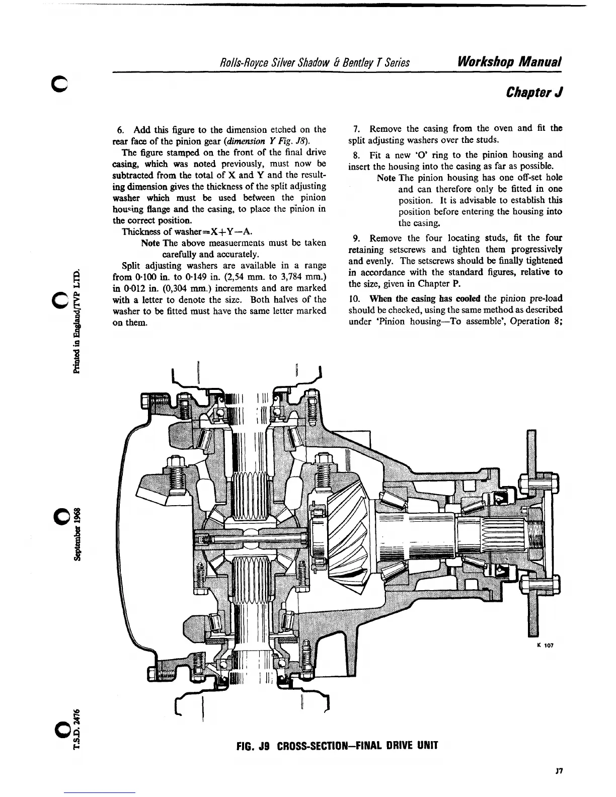
FIG.
J9
CROSS-SECTION-FINAL DRIVE UNIT