Workshop
Manual
Rolls- Royce Silver Shadow
8
Bentle y
T
Series
Chapter
M
3.
Repeat the test, replacing one of the two cables
by the third cable.
Fa~iure of the test lamp to
illuminate on either occasion, means that part of the
stator winding is open-circuit and the stator
must
be
renewed.
4.
Test for defective insulation between the stator
coils and lamination pack with the mains test lamp
(see
Fig.
M30).
5.
Connect the test probes between any one of the
three cable ends and the lamination pack. If the lamp
is illuminated, the stator coils are earthing and the
stator must be renewed.
6.
Before soldering the stator cable ends to the
diode pins, carry out the following test.
Diodes-To test
1.
Each diode can be checked if connected in
series with a 1.5 Watt test bulb across a 12 Volt
(D.C.)
supply. Test again by reversing the
connections
(see
Fig.
M3I).
2.
The bulb should be illuminated and current
should flow in one direction only. Should the bulb
be illuminated in both tests, or not be illuminated in
either test, this indicates a defective diode and the
appropriate heat sink assembly must be renewed.
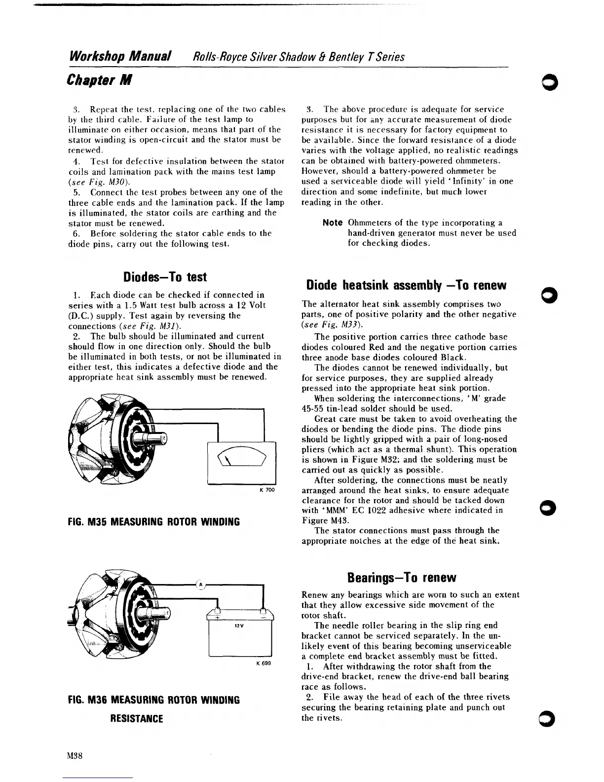
FIG. M35 MEASURING ROTOR WINDING
3.
The above procedure is adequate for service
purposes but for any accurate measurement of diode
resistance it is necessary for factory equipment to
be available. Since the forward
resis~ance of a diode
varies with the voltage applied, no realistic readings
can be obtained with battery-powered ohmmeters.
However, should a battery-powered ohmmeter be
used
a
serviceable diode will yield 'Infinity' in one
direction and some indefinite, but much lower
reading in the other.
Note
Ohmmeters of the type incorporating a
hand-driven generator must never be used
for checking diodes.
Diode heatsink assembly -To renew
The alternator heat sink assembly comprises two
parts, one of positive polarity and the other negative
(see
Fig.
M33).
The positive portion carries three cathode base
diodes coloured Red and the negative portion carries
three anode base diodes coloured Black.
The diodes cannot be renewed individually, but
for service purposes, they are supplied already
pressed into the appropriate heat sink portion.
When soldering the interconnections,
'
M'
grade
45-55
tin-lead solder should be used.
Great care must be taken to avoid overheating the
diodes or bending the diode pins. The diode pins
should be lightly gripped with a pair of long-nosed
pliers (which act as a thermal shunt). This operation
is shown in Figure
M32;
and the soldering must be
carried out as quickly as possible.
After soldering, the connections must be neatly
arranged around the heat sinks, to ensure adequate
clearance for the rotor and should be tacked down
with
'MMM'
EC 1022 adhesive where indicated in
Figure
M43.
The stator connections must pass through the
appropriate
no~ches at the edge of the heat sink.
Bearings-To renew
Renew any bearings which are worn to such an extent
that they allow excessive side movement of the
rotor shaft.
The needle roller bearing in the slip ring end
bracket cannot be serviced separately. In the un-
likely event of this bearing becoming unserviceable
a complete end bracket assembly must be fitted.
K
699
1.
After withdrawing the rotor shaft from the
drive-end bracket, renew the drive-end ball bearing
race as follows.
FIG. 111136 MEASURING ROTOR WINDING
2.
File away the head of each of the three rivets
securing the bearing retaining plate and punch out
RESISTANCE
the rivets.
3