Rolls- Royce Silver Shadow
6
Bentley
T
Series
Workshoa
Manual
Chapter
K
Fuel pump failure
In the United Kingdom all faulty pumps are recondi-
tioned by the manufacturer only; it is therefore
necessary to replace a faulty
unlt with a new or recondi-
tioned unit.
In all other countries, a new or reconditioned pump
should be fitted; if this is not possible, parts can be
obtained and the fault rectified as described in Section
K6-Fault Diagnosis.
All reconditioned pump units and parts are obtain-
able through the Parts Department at Crewe.
Reconditioned fuel pump units
S.U.
reconditioned fuel pump units are of the short
barrel type and incorporate all the latest design
features. The pump mounting studs are
either
of B.S.F.
or U.N.F. thread form, but the correct nuts will be
supplied with each pump. Nuts from other pumps
should not be fitted unless the thread form is known
to be the same as the stud thread on the reconditioned
Pump.
Neither inlet or outlet unions are supplied with
reconditioned pumps. These parts should be removed
from the faulty pump unit before its return to
Rolls-
Royce Limited.
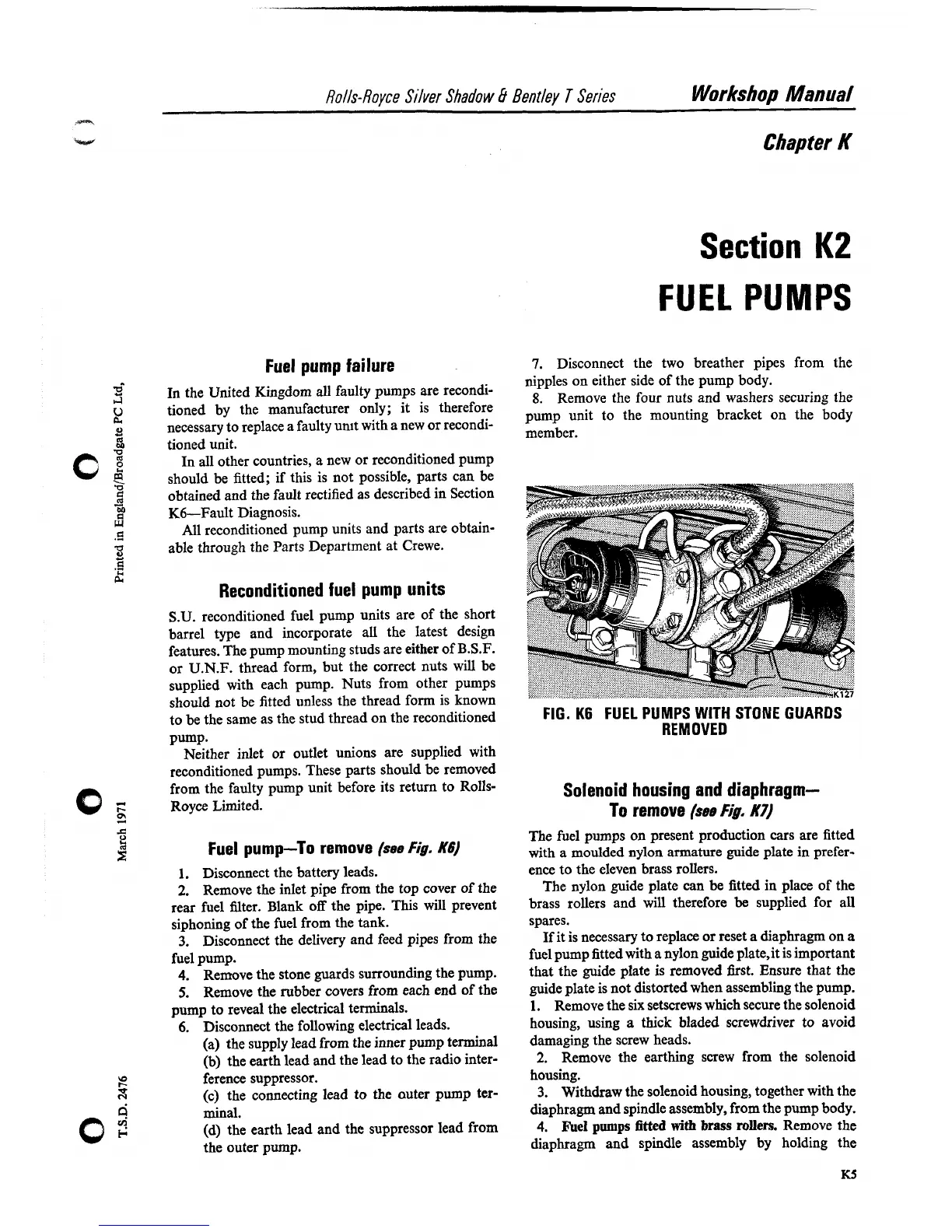
Fuel pump-To remove
(see
Fig.
K6)
1.
Disconnect the battery leads.
2.
Remove the inlet pipe from the top cover of the
rear fuel filter. Blank off the pipe. This will prevent
siphoning of the fuel from the tank.
3.
Disconnect the delivery and feed pipes from the
fuel pump.
4. Remove the stone guards surrounding the pump.
5.
Remove the rubber covers from each end of the
pump to reveal the electrical terminals.
6.
Disconnect the following electrical leads.
(a) the supply lead from the inner pump terminal
(b) the earth lead and the lead to the radio inter-
ference suppressor.
(c) the connecting lead to the auter pump ter-
minal.
(d) the earth lead and the suppressor lead from
the outer pump.
Section
K2
FUEL
PUMPS
7.
Disconnect the two breather pipes from the
nipples on either side of the pump body.
8.
Remove the four nuts and washers securing the
pump unit to the mounting bracket on the body
member.
FIG.
K6
FUEL PUMPS
WITH STONE
GUARDS
REMOVED
Solenoid housing
and
diaphragm-
To
remove
(see
Fig.
K7)
The fuel pumps on present production cars are fitted
with a moulded nylon armature guide plate in prefer-
ence to the eleven brass rollers.
The nylon guide plate can be fitted
in
place of the
brass rollers and will therefore
be
supplied for all
spares.
If it is necessary to replace or reset a diaphragm on
a
fuel pump fitted with a nylon guide plate3 is important
that the guide plate is removed first. Ensure that the
guide plate is not distorted when assembling the pump.
1.
Remove the six setscrews which secure the solenoid
housing, using
a
thick bladed screwdriver to avoid
damaging the screw heads.
2.
Remove the earthing screw from the solenoid
housing.
3.
Withdraw the solenoid housing, together with the
diaphragm and spindle assembly, from the pump body.
4.
Fuel
pumps
fitted
with
brass rollers.
Remove the
diaphragm and spindle assembly by holding the