Rolls-Royce Silver Shadow
8
Bentley
T
Series
Workshop
Manual
Chapter
M
Section
MI5
RADIO RECEIVER, CARTRIDGE PLAYER,
LOUDSPEAKERS AND AERIAL
Receiver-To remove
Left and right-hand drive cars prior to
Car Serial Numbers 6000
&
6791
1.
Disconnect the battery.
2.
Pull off the control knobs from their spindles.
(it is not necessary to remove the aerial and balance
control knobs). Remove the spindle lock nuts and
receiver
facia finisher.
3.
Unscrew and remove the two screws securing
the receiver trim to the under-facia.
4.
Lower the rear of the receiver trim and
simultaneously withdraw the front of the trim clear
of the receiver control spindles
(see
Fig.
M89).
5.
Disconnect the receiver current supply by dis-
connecting the in-line
'
Lucar' connection (Green/
Brown); ensure that the blade remains in the fuse
lead.
6.
Disconnect the loudspeaker connections from
the in-line 'Lucar' connector block.
7.
Remove the aerial lead from the receiver socket.
8.
Unscrew and remove the four screws securing
the receiver to the mounting brackets;
accessibility may be improved if the brackets are
completely removed.
Re ceiver-To remove
Left and right-hand drive cars
from
Car Serial Numbers 6000
&
6791
1.
Disconnect the battery.
2.
Pull the control knobs off their spindles.
Unscrew and remove the spindle lock-nuts.
3.
Right-hand drive cars only,
remove the two
screws securing the air conditioning unit control
knobs, remove the two screws securing the wooden
facia panel and carefully lift off.
f eft-hand
drive cars only,
carefully lift off
the
wooden facia panel.
5.
Disconnect the receiver current supply by
disconnecting the in-line
'
Lucar' connection
(Brown/Green).
6.
Disconnect the loudspeaker connections by
disconnecting the in-line
'
Lucar' connections and
remove the aerial lead from the receiver.
7.
Unscrew and remove the four extended-head
setscrews securing the receiver brackets to the
console.
8.
Carefully withdraw the lead connection plugs
for the air conditioning unit control switches and lay
the plugs safely within the console.
9.
Remove the two setscrews securing the receiver
brackets to the receiver.
10.
Carefully manoeuvre the receiver out of the
console.
4.
Carefully prise away, using a flat tool, the
triangular trim pads situated one each side of the
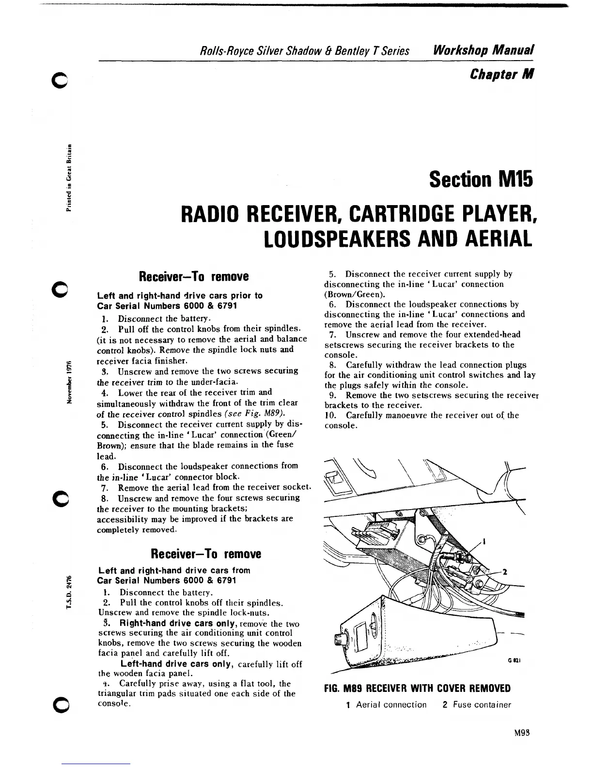
FIG.
M89 RECEIVER
WITH
COVER REMOVED
console.
1
Aerial connection
2
Fuse container
M93