www.dadehpardazan.ir 88594014-15
5.2 Basic Functions Settings
5-11
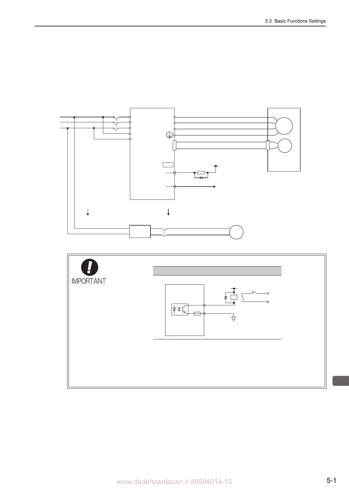
(1) Wiring Example
Use the brake signal (/BK) and the brake power supply to form a brake ON/OFF circuit. The following dia-
gram shows a standard wiring example.
The timing can be easily set using the brake signal (/BK).
Note: A brake and its power supply are not included.
• Configure the relay circuit to apply th
e holding brake by the emergency stop.
• The brake signal (/BK) cannot be used with
factory settings. The output signal must
be allocated. Refer to (3) Brake Signal (/BK) Allocation to set the parameter Pn50F.
• When using a 24-V brake, separate the 24-VDC power supply from other power sup-
plies, such as the one used for the I/O sign
als of CN1 connectors. Always install the
24-VDC power supply separately. If the power supply is shared, the I/O signals might
malfunction.
M
ENC
U
V
W
CN2
AC DC
BK-RY
BK-RY
+24 V
L1
L2
L3
L1C
L2C
(/BK+)
(/BK-)
CN1
1D
0 V
Servomotor
SERVOPACK
Power supply
Brake power
supply
DC side
AC side
BK
0V
Emergency stop
5 to 24 VDC
SERVOPACK
Photocoupler
 Loading...


