4.2 Using the Digital LED Operator
112 YASKAWA TM.V1000.01 V1000 Drive Installation & Start-Up Manual (Preliminary 01-19-07)
The Setup Group within the Programming Mode
In Setup Group, the user can access the minimum group of parameters required to
operate the application.
Note: Setup Group parameters are listed in Appendix B, and are indicated with the letter
“S” in the Access Level column.
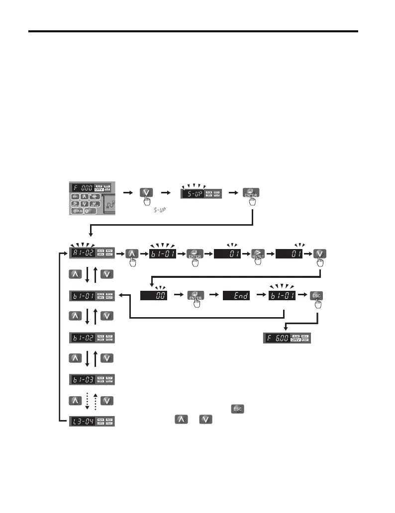
Figure 4.5 illustrates the keys to press to enter the Setup Group.
In this example, the source of the frequency reference is changed from the control
circuit terminals to the LED Operator (i.e., b1-01 is changed from 1 to 0).
Figure 4. 5
Figure 4.5 Setup Group Example
STOP
Control Circuit Terminal
Select digit
to edit
Press until ޓޓ
appears
Parameter Display
LED Operator
Frequency reference
appears when powered up
Parameter Display
*1 Move to the right to change parameter settings. Scroll down to view
and check settings in the Setup Mode.
*2 To return to the Top Menu, press . To view or edit other parameters,
press and .

 Loading...


