4.4 Basic Parameter Adjustments
128 YASKAWA TM.V1000.01 V1000 Drive Installation & Start-Up Manual (Preliminary 01-19-07)
User Defined and Variable Carrier Frequency
If parameter C6-02 is set to F, any carrier frequency value between the fixed values
can be set.
In Open Loop Vector and PM motor control the desired value can be set in
parameter C6-03.
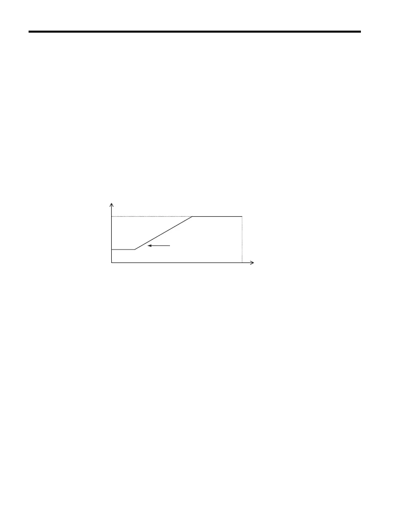
In V/f control the carrier frequency can be set up to change linearly with the output
frequency. In this case the upper and lower limits for the carrier frequency and the
carrier frequency proportional gain (C6-03, C6-04, C6-05) have to be set up like
shown Figure 4.11.
Note: Set both C6-03 and C6-04 to the same value or set C6-05 to 0 to keep the carrier
frequency at a constant level without changing.
Figure 4.11
Figure 4.11 Carrier Frequency Changes Relative to Output Frequency
Carrier Frequency Setting Error (OPE11)
A carrier frequency setup error (OPE11) will occur under the following conditions:
• Carrier frequency gain (C6-05) is greater than 6 and C6-03 < C6-04.
• Duty Selection is set to Heavy Duty (C6-01 = 0) while the carrier frequency is
restricted from alteration (C6-02 = E).
• C6-01 is set to 1 and C6-02 is set to E
Note: Refer to Troubleshooting on page 183 for more information on operator errors
(OPE).
C6-03
C6-04
output frequency
E1-04
maximum output frequency
* The value of coefficient K is determined by the value of C6-03.
C6-03 ҈ 10.0 kHz㧦K=3
10.0 kHz > C6-03 ҈ 5.0 kHz㧦K=2
5.0 kHz > C6-03㧦K=1
carrier frequency
output frequency
× (C6-05) × K

 Loading...


