4.4 Basic Parameter Adjustments
YASKAWA TM.V1000.01 V1000 Drive Installation & Start-Up Manual (Preliminary 01-19-07) 159
Start-Up Programming &
Operation
4
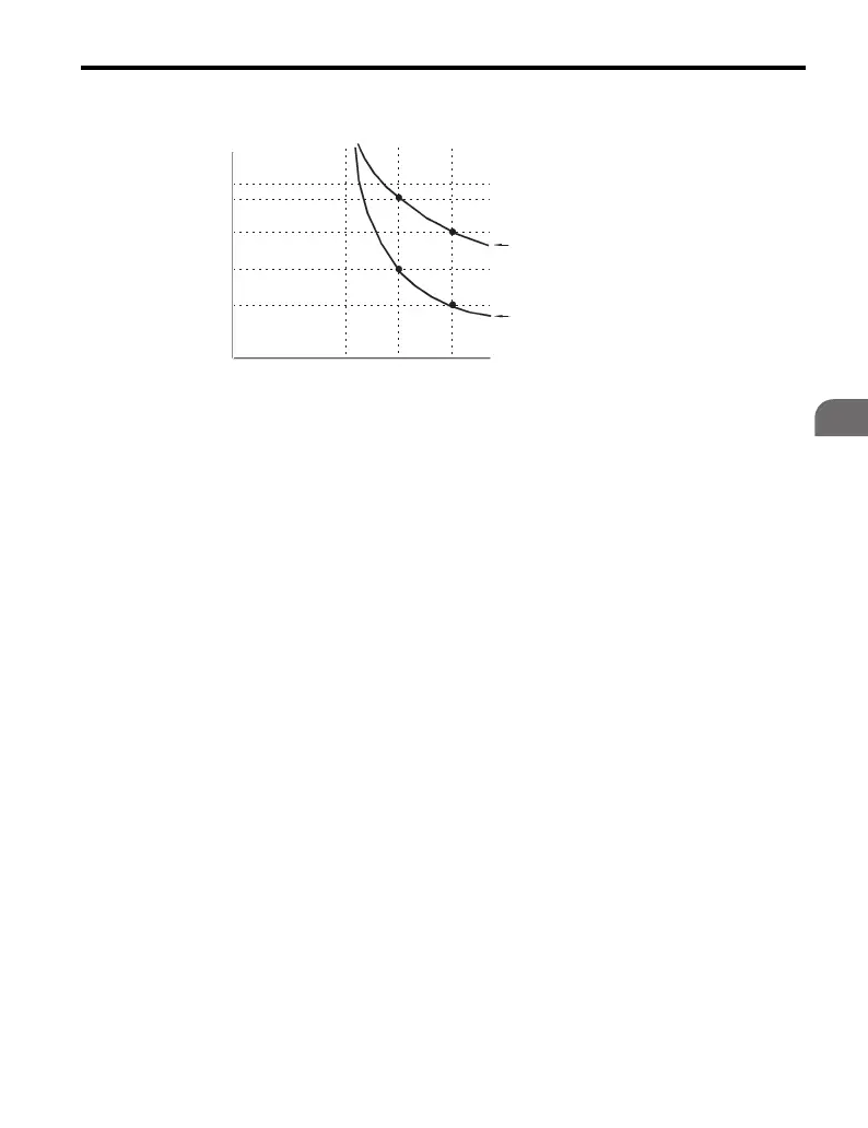
Note: Figure 4.26 illustrates motor protection operation time characteristics.
Figure 4.26
Figure 4.26 Motor Protection Operation
• Disable motor protection (L1-01 = 1) when running multiple motors from the
same drive. Install a properly sized external overload device with each motor to
satisfy national and local electrical code.
• Motor protection may not be possible even if enabled (L1-01 = 1) in applications
where the power is frequently removed from the drive. This is because thermal
calculations are reset every time the power is cycled.
• Motor cooling capacity may be affected by operating frequency. This is typically
the case with motors incorporating shaft mounted cooling fans. Motor overload
trips may be experienced even though the motor current is less than motor rated
current when operating at frequencies less than 50 Hz. This occurs due to the
drives ability to alter the overload level based on operating frequency. Therefore,
use a motor that is suitable for the intended load and speed range, and set the
overload protection (L1-01) to the appropriate setting.
Cold Start
Hot Start
Motor Current (%)
E2-01 = 100%
10
7
3
1
0.4
0.1
0 100 200150
Operation Time (minutes)

 Loading...


