4.6 Test Run Checklist
182 YASKAWA TM.V1000.01 V1000 Drive Installation & Start-Up Manual (Preliminary 01-19-07)
Proceed to the following checklist after checking items 4 through 9.
No. Checklist Page
10
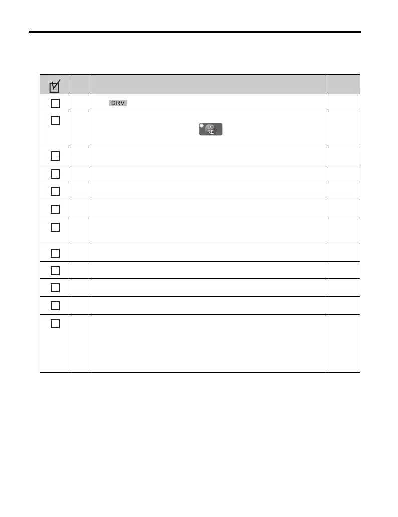
The should illuminate after giving a run command.
11
If the run command and frequency reference are provided via the LED operator,
the LO/RE light should be lit. Press to switch between LOCAL and
REMOTE.
115
12
If the motor rotates in the opposite direction during the test run, switch two of the
drive output terminals (U/T1, V/T2, W/T3).
160
13 Select the correct duty rating (C6-01) for the application. 125
14
Set the correct values for the motor rated current (E2-01) and the motor protection
selection (L1-01) to ensure motor thermal protection.
157
15
If the run command and frequency reference are provided via the control circuit
terminals, set the drive for REMOTE and be sure the LO/RE light is out.
115
16
If the control circuit terminals should supply the frequency reference, select the
correct voltage input signal level (0 to 10 V) or the correct current input signal
level (4 to 20 mA).
115
17 Set the proper voltage to terminal A1. (0 to 10 V) 131
18 Set the proper current to terminal A2. (4 to 20 mA) 131
19
Set parameters H3-09 and H3-10 to the proper input signal values when using
analog input terminals A1 and A2.
131
20
Set DIP switch S1 to the V position when using 99 voltage input to the terminal
board.
131
21
Set the minimum and maximum frequency references to the desired values. Make
the following adjustments if the drive does not operate as expected:
Voltage input, 0 to 10 V: For terminal A1, adjust the frequency reference gain
(H3-03) until reaching the desired value (60 Hz).
Current input, 4 to 20 mA: For terminal A2, adjust the current bias (H3-12) until
the frequency reference reaches 0.0 Hz. Next adjust the current gain (H3-11) until
the frequency reference reaches 60 Hz.

 Loading...


