EasyManuals Logo

YASKAWA V1000 Series Installation & Start-Up Manual

YASKAWA V1000 Series
470 pages
To Next Page IconTo Next Page
To Previous Page IconTo Previous Page
Page #201 background imageLoading...
Page #201 background image
5.4 Drive Alarms, Faults, and Errors
YASKAWA TM.V1000.01 V1000 Drive Installation & Start-Up Manual (Preliminary 01-19-07) 201
Troubleshooting
5
Auto-Tuning Errors
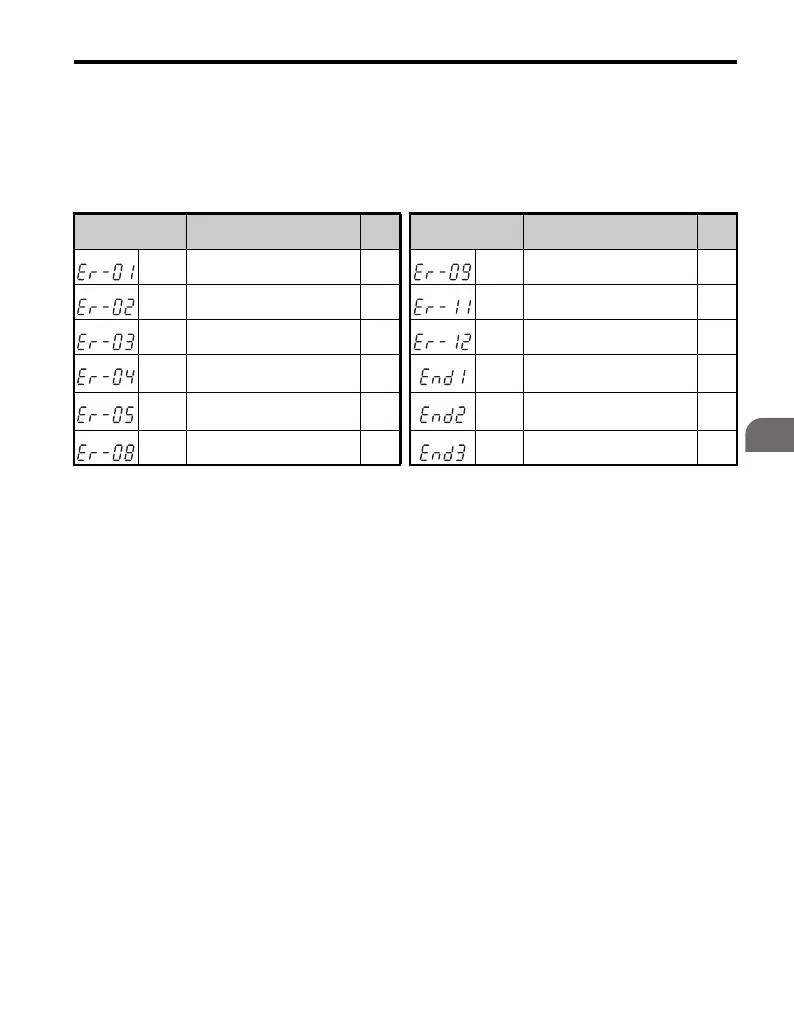
Auto-Tuning errors occur during Auto-Tuning in drive set-up. Table 5.8 illustrates
the LED operator display for tuning errors.
Table 5.8 Auto-Tuning Error Displays
LED Operator
Display
Name Page
LED Operator
Display
Name Page
Er-01 Motor Data Error 241 Er-09 Acceleration Error 243
Er-02 Alarm 241 Er-11 Motor Speed Error 243
Er-03 STOP button Input 242 Er-12 Current Detection Error 243
Er-04
Line-to-Line Resistance
Error
242 End1 Excessive V/f Setting 243
Er-05 No-Load Current Error 242 End2
Motor Iron Core Saturation
Coefficient Error
244
Er-08 Rated Slip Error 242 End3 Rated Current Setting Alarm 244

Table of Contents

Other manuals for YASKAWA V1000 Series

Questions and Answers:

Question and Answer IconNeed help?

Do you have a question about the YASKAWA V1000 Series and is the answer not in the manual?

YASKAWA V1000 Series Specifications

General IconGeneral
ModelV1000 Series
SeriesV1000
Output Frequency0.1 to 400 Hz
Overload Capacity150% for 60 seconds
TypeAC Drive
Control MethodV/f Control
Input Voltage200-240V, 380-480V
Output Voltage0 to Input Voltage
Power Range0.1 to 18.5 kW
Horsepower0.2 to 25 HP
Protection FeaturesOvercurrent, Overvoltage, Undervoltage, Overheating, Short Circuit, Ground Fault
Communication InterfacesModbus RTU
EnclosureIP20
Ambient Temperature-10 to +50°C
Storage Temperature-20 to +60°C
Humidity5 to 95% RH (non-condensing)
Cooling MethodFan Cooled

Related product manuals