6.5 Drive Replacement
YASKAWA TM.V1000.01 V1000 Drive Installation & Start-Up Manual (Preliminary 01-19-07) 285
Periodic Inspection &
Maintenance
6
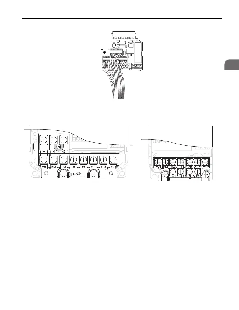
Figure 6.9
Figure 6.9 Terminal Board Removed
4. Disconnect main motor and power wiring from terminals R/L1, S/L2, T/L3,
U/T1, V/T2, W/T3, and ground wiring.
Figure 6.10
Figure 6.10 Main Circuit Terminal Block Configurations
5. Loosen the screw on the terminal cover (Figure 6.11, B) to remove the
terminal cover and expose the conduit bracket (Figure 6.11, A).

 Loading...


