B.2 Parameter Table
YASKAWA TM.V1000.01 V1000 Drive Installation & Start-Up Manual (Preliminary 01-19-07) 339
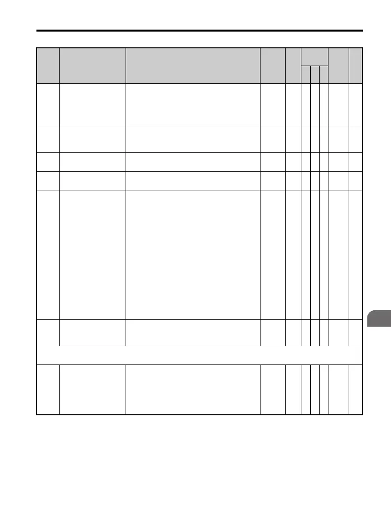
Parameter List
B
b3-14
Bi-Directional Speed
Search Selection
This parameter enables the drive to detect
motor direction during speed search.
0: Disabled–Drive uses frequency reference
direction.
1: Enabled–Drive uses detected direction.
0,1 0 A A − 19E —
b3-17
Speed Search Restart
Current Level
Sets the speed search restart operation detection
current level in percentage units. The drive's
rated current is set at 100%
0 to 200
150
%
AA− 1F0 —
b3-18
Speed Search Restart
Detection Time
Sets the time in seconds for speed search restart
to be detected.
0.00 to
1.00
0.10
s
AA− 1F1 —
b3-19
Number of Speed
Search Restarts
Sets the number of restarts possible for speed
search restart operations.
0 to 10 3 A A − 1F2 —
b3-24
Speed Search Method
Selection
Sets the speed search method used at start-up
and after a momentary power loss.
0: Current Detection Type
1: Speed Estimation Type
Parameter b3-01 enables this function at start,
and parameter L2-01 enables this function
during momentary power loss.
Current Detection Type - Start speed search
from max frequency or from the frequency
when momentary power loss occurred. Detects
motor speed based on the current level
(conventional method).
Speed Estimation Type - Estimates the motor
speed when speed search begins. Accelerates or
decelerates to the estimated frequency. Works
in both forward and reverse.
0,1 0 A A − 1C0 —
b3-25
Speed Search Retry
Interval Time
Sets waiting time until the search retry
operation beginning when searching for the
speed of PM in 0.1 seconds.
0 to 30.0 0.5 s A A A 1C8 —
b4: Timer Function
Use b4 parameters to configure timer function operation.
b4-01
Timer Function
On-Delay Time
Used in conjunction with a multi-function
digital input (H1- = 18) and a multi-
function digital output (H2- = 12)
programmed for the timer function. This sets
the amount of time between digital input
closure and digital output activation.
0.0 to
300.0
0.0 s A A A 1A3 —
No. Name Description Range Def.
Control
Mode
Addr.
Hex
Pg.
V/f
O
LV
P
M

 Loading...


