B.2 Parameter Table
340 YASKAWA TM.V1000.01 V1000 Drive Installation & Start-Up Manual (Preliminary 01-19-07)
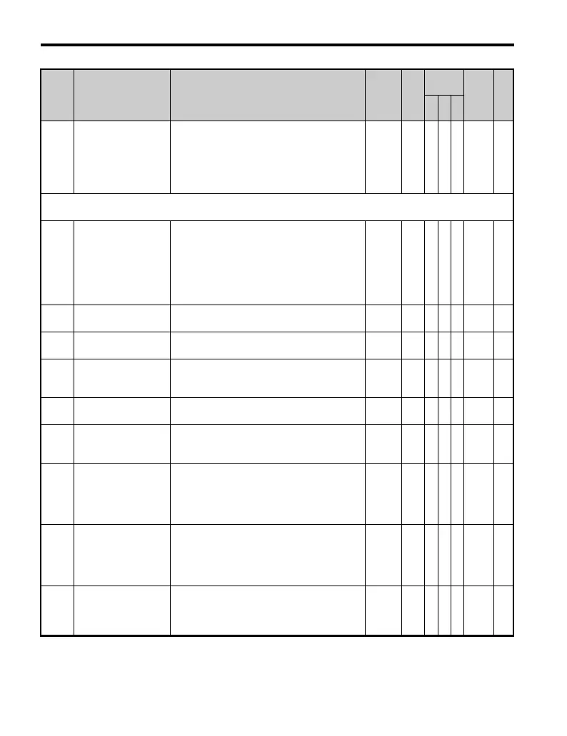
b4-02
Timer Function
Off-Delay Time
Used in conjunction with a multi-function
digital input (H1- = 18) and a multi-
function digital output programmed for the
timer function. This sets the amount of time the
output remains activated after the digital input
is opened.
0.0 to
300.0
0.0 s A A A 1A4 —
b5: PID Control
Use b5 parameters to configure the PID control drive function.
b5-01 PID Function Setting
This parameter sets the function of the PID
control.
0: Disabled
1: D = Feedback
2: D = Feed-Forward
3: Freq. Ref. + PID output (D = Feedback)
4: Freq. Ref. + PID output (D = Feed-Forward)
0 to 4 0 A A A 1A5 —
b5-02
<22>
Proportional Gain
Setting (P)
Sets the proportional gain of the PID controller.
0.00 to
25.00
1.00 A A A 1A6 —
b5-03
<22>
Integral Time Setting
(I)
Sets the integral time for the PID controller. A
setting of 0 disables integral control.
0.0 to
360.0
1.0 s A A A 1A7 —
b5-04
<22>
Integral Limit Setting
Sets the maximum output possible from the
integrator. Set as a percentage (%) of maximum
frequency.
0.0 to
100.0
100.0
%
AAA 1A8 —
b5-05
<22>
Derivative Time
Sets D control derivative time. A setting of 0.00
seconds disables derivative control.
0.00 to
10.00
0.00
s
AAA 1A9 —
b5-06
<22>
PID Output Limit
Sets the maximum output possible from the
entire PID controller. Set as a percentage (%) of
maximum frequency.
0.0 to
100.0
100.0
%
AAA 1AA —
b5-07
<22>
PID Offset
Adjustment
Sets the amount of offset of the output of the
PID controller. Set as a percentage (%) of
maximum frequency. The offset is summed
with the PID output. This can be used to
artificially advance a slow starting PID loop.
-100.0 to
+100.0
0.0% A A A 1AB —
b5-08
<22>
PID Primary Delay
Time Constant
Sets the amount of time for the filter on the
output of the PID controller. Note: The offset is
summed with the PID output. This can be used
to artificially advance a slow starting PID loop.
Note: Normally, change is not required.
0.00 to
10.00
0.00
s
AAA 1AC —
b5-09
PID Output Level
Selection
Sets the PID controller for direct or reverse
acting.
0: Normal Output (direct acting)
1: Reverse Output (reverse acting)
0,1 0 A A A 1AD —
No. Name Description Range Def.
Control
Mode
Addr.
Hex
Pg.
V/f
O
LV
P
M

 Loading...


