B.2 Parameter Table
360 YASKAWA TM.V1000.01 V1000 Drive Installation & Start-Up Manual (Preliminary 01-19-07)
E2-12
Motor
Iron-Core
Saturation
Coefficient 3
Set to the motor iron saturation coefficient at
130% of magnetic flux.
This value is automatically set during
rotational Auto-Tuning.
1.30 to
5.00
1.30 − A − 328 —
E3: Motor 2 V/f Characteristics
Use E3 parameters to set the V/f pattern for a second motor.
E3-01
Motor 2
Control
Method
Selection
0: V/f Control
2: Open Loop Vector (OLV)
Motor 2 cannot be a Permanent Magnet
Motor (PM).
Set this parameter according to L1-01 to
protect the motor from overload (shared with
the primary motor).
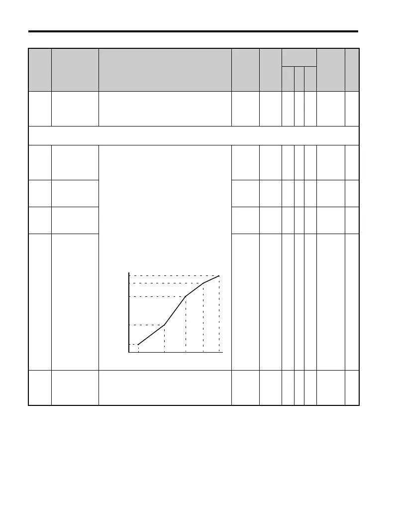
To set linear V/f characteristics, set the same
values for E3-07 and E3-09. In this case, the
setting for E3-08 will be disregarded. Ensure
that the four frequencies are set according to
these rules or OPE10 fault will occur:
E3-04 (FMAX) ≥ E3-06 (FA)
> E3-07 (FB) > E3-09 (FMIN)
0 to 4 0 A A − 319 —
E3-04
Motor 2 Max
Output
Frequency
40.0 to
400.0
<20>
60 Hz
<2>
<35>
AA− 31A —
E3-05
Motor 2 Max
Voltage
(VMAX)
0.0 to
255.0
<24>
200.0
V
<2>
AA− 31B —
E3-06
Motor 2 Base
Frequency
(FA)
0.0 to
400.0
60 Hz
<2>
AA− 31C —
E3-07
Motor 2 Mid
Output
Frequency
(FB)
0.0 to
400.0
3.0 Hz
<2>
AA− 31D —
No. Name Description Range Def.
Control
Mode
Addr.
Hex
Pg.
V/f
O
L
V
P
M
VACrms Out (V)
Frequency (Hz)
E3-09 E3-07 E3-06 E3-11 E3-04
E3-05
E3-12
E3-13
E3-08
E3-10

 Loading...


