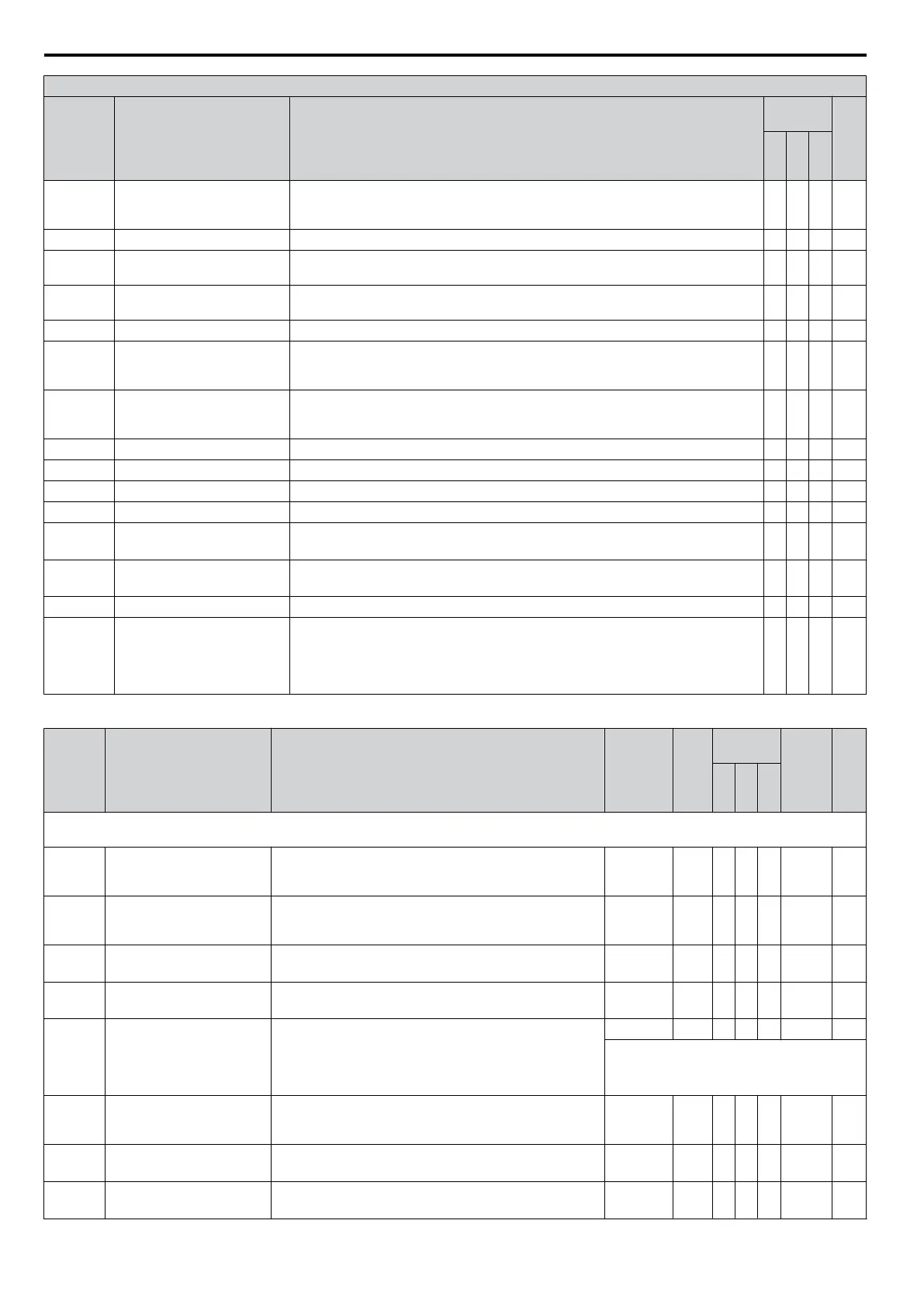
H2 Multi-Function Digital Output Settings
H2-oo
Setting
Function Description
Control
Mode
Pg.
V/
f
O
L
V
P
M
37 During Frequency Output
Open: No frequency output from drive if stopped, with baseblock, with DC injection
braking during initial excitation, or with short-circuit braking.
Closed: Drive is outputting a frequency
O O O 193
38 Drive Enable
Closed: Multi-function input closes (H1-oo = 6A)
O O O 194
39 Watt Hour Pulse Output
Output units are determined by H2-06, outputs 200 ms pulse for each incremented
kWh count.
O O O 194
3C LOCAL/REMOTE Status
Closed: LOCAL
Open: REMOTE
O O O 194
3D Speed Search Closed: Speed search is being executed. O O O 194
3E PID Feedback Loss Low
Closed: PID Feedback Loss Low.
PID feedback value is below the level set to b5-13 for longer than the time set in
b5-14.
O O O 194
3F PID Feedback Loss High
Closed: PID Feedback Loss High.
PID feedback value exceeds the level set to b5-36 for longer than the time set to
b5-37.
O O O 194
4A KEB Operation Closed: KEB is being performed. O O O 194
4B Short-Circuit Brake Closed: Short-Circuit Braking is active. − − O 194
4C During Fast-stop Closed: Fast-stop command is entered O O O 194
4D oH Pre-alarm Time Limit Closed: oH Pre-alarm time limit is passed. O O O 194
4E
<1>
Braking Transistor Fault (rr) Closed: The built-in dynamic braking transistor failed. O O O 194
4F
<1>
Braking Resistor Overheat
(oH)
Closed: The dynamic braking resistor has overheated. O O O 194
90 to 92 DWEZ Digital Outputs 1 to 3 Reserved for DWEZ digital output functions. O O O 194
100 to 192
H2 Parameter Functions
Reversed
Output Switching of
0 to 92
Reverse the output switching of
the multi-function output functions. Set the last two
digits of 1oo to reverse the output signal of that specific function.
Examples:
Setting “108” reverses the output of “During baseblock,” which is setting value 08.
Setting “14A” reverses the output of “During KEB
operation”, which is setting “4A”.
O O O 195
<1> Available in drive software versions PRG: 1016 and later.
No. Name Description Range Def.
Control
Mode
Addr.
Hex
Pg.
V/
f
O
L
V
P
M
H3: Analog Inputs
Use H3 parameters to set the multi-function analog input terminals.
H3-01
Terminal A1 Signal Level
Selection
Sets the input level for terminal A1.
0: 0 to +10 V (lower limit)
1: 0 to +10 V (no lower limit)
0, 1 0 A A A 410 195
H3-02
Terminal A1 Function
Selection
Sets the function of terminal A1.
When terminal A1 is not used or is used as a through
terminal, this parameter must be set to “F”.
0 to 31
<1>
0 A A A 434 196
H3-03
<2>
Terminal A1 Gain Setting
Sets the level of the input value selected in H3-02 when 10
V is input at terminal A1.
-999.9 to
999.9
100.0
%
A A A 411 196
H3-04
<2>
Terminal A1 Bias Setting
Sets the level of the input value selected in H3-02 when 0
V is input at terminal A1.
-999.9 to
999.9
0.0% A A A 412 196
H3-09
Terminal A2 Signal Level
Selection
Sets the input signal level for terminal A2.
0: 0 to +10 V (with lower limit)
1: 0 to +10 V (no lower limit)
2: 4 to 20 mA
3: 0 to 20 mA
0 to 3 2 A A A 417 197
Use DIP switch S1 to set input terminal A2 for
a current or a voltage input signal.
H3-10
Terminal A2 Function
Selection
Sets the function of terminal A2.
When terminal A2 is not used or is used as a through
terminal, this parameter must be set to “F”.
0 to 31
<1>
0 A A A 418 198
H3-11
<2>
Terminal A2 Gain Setting
Sets the level of the input value selected in H3-10 when 10
V (20 mA) is input at terminal A2.
-999.9 to
999.9
100.0
%
A A A 419 198
H3-12
<2>
Terminal A2 Bias Setting
Sets the level of the input value selected in H3-10 when 0
V (0 or 4 mA) is input at terminal A2.
-999.9 to
999.9
0.0% A A A 41A 198
B.2 Parameter Table
354
YASKAWA ELECTRIC SIEP C710606 16C YASKAWA AC Drive – V1000 Technical Manual

 Loading...


