2 Installation and Commissioning, IRC5
2.9.7. Installation of Euromap and SPI
1293HAC021313-001 Revision: K
© Copyright 2004-2008 ABB. All rights reserved.
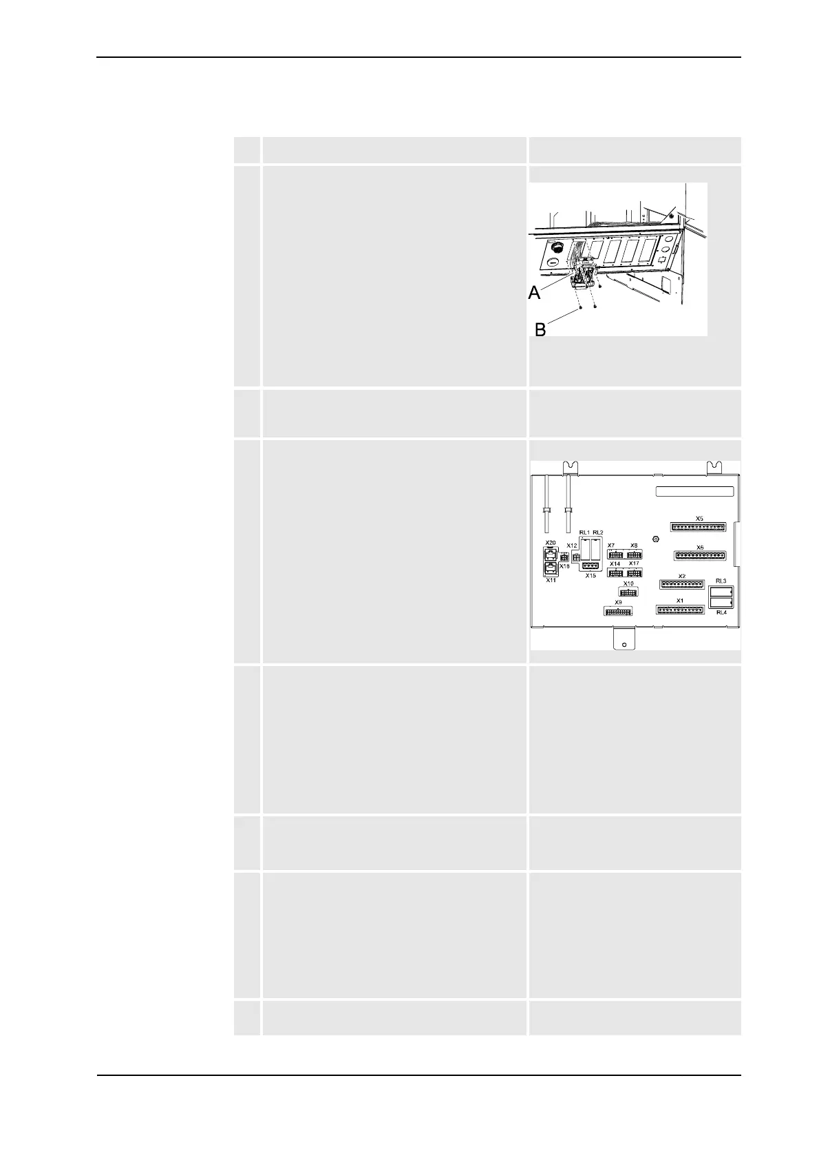
5. Fit the harness through the connector hole on
the adapter plate, and fit the connector XS13
with the attachment screws.
xx0600002654
• A: connector XS13
• B: attachment screw (4 pcs)
6. Route the cables to the panel board connectors
in the existing straps according to the illustra-
tion.
See the illustration inLocation of
Euromap harness in the Dual Cabinet
on page 124
7. Connect the connectors X1, X2 and X5 on the
panel board.
xx0500001890
8. Connect the wires no. 1002 and no. 1019 to the
light barrier and safety relay.
"Mould area free" (Euromap) or
"Enable Clamp motion" (SPI) signal.
This is a important signal that tells the
injection moulding machine (IMM)
that nothing is in its workarea.
This signal can be connected in
several ways.
Our recommendation is to connect it
to the light barrier and safety relay.
9. Connect the wires to the additional fuse:
•wire no. 1032 to XT31.2
•wire no. 1046 to XT31.4
See the location of the additional fuse
in Location of Euromap harness in the
Dual Cabinet on page 124.
10. Connect the wires to I/O 1.
•wire no. 1053 to X1.10
• wire no. 1054 to X2.10
• wire no. 1055 to X3.9
•wire no. 1056 to X4.9
•wire no. 1057 to X1.9
•wire no. 1058 to X2.9
See the location of I/O 1 in Location of
Euromap harness in the Dual Cabinet
on page 124.
11. Fit the 24K1 and 24K2 relays on the mounting
rail on the cabinet door.
See Location of Euromap harness in
the Dual Cabinet on page 124.
Action Note/Illustration
Continued
Continues on next page