2 Installation and Commissioning, IRC5
2.5.14. Connection of servo disconnect, by servo power switch
3HAC021313-001 Revision: K80
© Copyright 2004-2008 ABB. All rights reserved.
2.5.14. Connection of servo disconnect, by servo power switch
General
The IRC5 controller is pre-wired to accept a customer servo disconnect.
NOTE!
Due to risk of voltage drop, the switch to the servo disconnect circuit should not be mounted
more than 50 meters from the Drive Module.
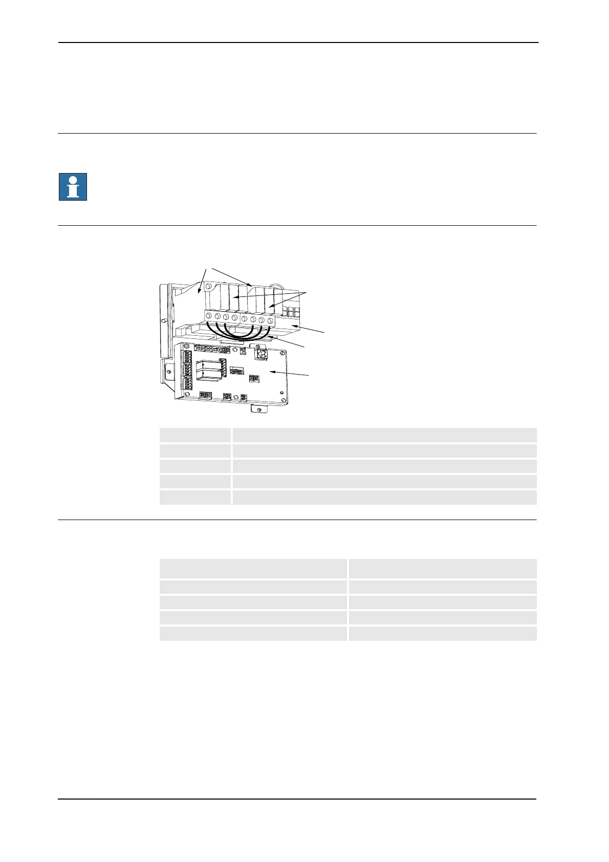
Location
The contactor is found on the left hand side inside the Drive Module as shown below.
xx0400001058
Required equipment
The table below details the required equipment.
A MOTOR ON contactor K42 / K43
B Contactor block3
C Brake contactor
D Jumper (4 pcs)
E Contactor interface board
B
D
E
Equipment Note
Wire AWG 10, brake AWG 16
Switch 500V 40 A, brake 24V 10A
Standard toolkit
Circuit Diagram See Circuit Diagram on page 341
Continues on next page