2 Installation and Commissioning, IRC5
2.5.10. The MOTORS ON/MOTORS OFF circuit
713HAC021313-001 Revision: K
© Copyright 2004-2008 ABB. All rights reserved.
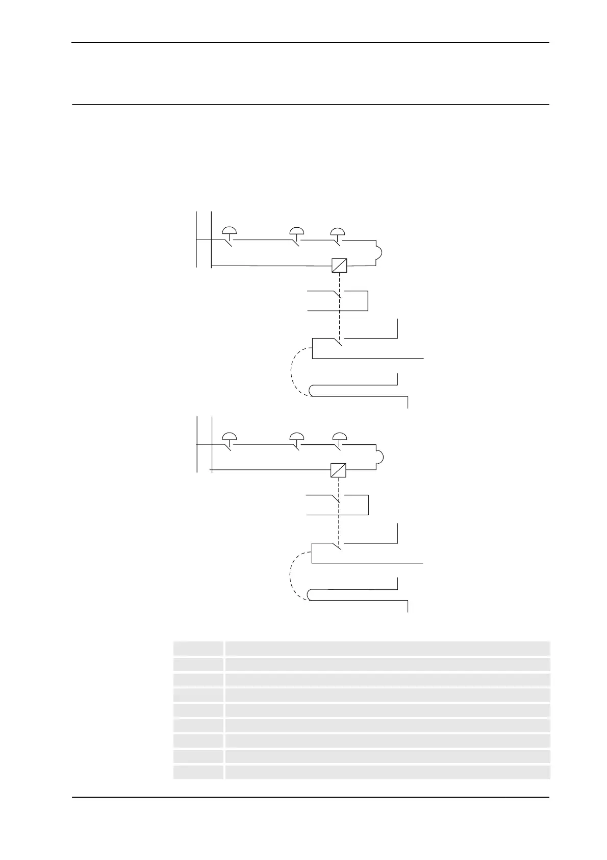
Connection of ES1/ES2 on panel unit
The diagram below shows the terminals for the emergency circuits.
The supply from internal 24V (X1/X2:10) and 0V (X1/X2:10) is displayed. For an ext.
supply, X1:3 / X2:9 is connected to ext. 24V, and X1:9 / X2:3 is connected to ext. 0V (dotted
lines).
xx0100000191
A Internal
B Ext stop
C FlexPendant
D Cabinet
E ES1 internal
F Run chain 1 top
G Internal
H ES2 internal
J Run chain 2 top
24V
24V
0V
0V
1:4
X1:8
X1:3
X1:7
X1:9
X1:10
X1:1
X1:2
24V
BCD
D
X1:6
E
24V
X2:9
X2:10
X2:1
X2:2
0V
X2:6
F
B
0V
X2:4
X2:5
C
2:4
G
X2:3
X2:8 X2:7
X1:4
X1:5
Continued
Continues on next page