Prepared by, date:
44
We reserve all rights in this document and in the information contained therein.Reproduction, use or
disclosure to third parties without express authority is strictly forbidden. © Copyright 2003 ABB
Page 43
48Total
3HAC024120-004
Latest revision:
Approved by, date:
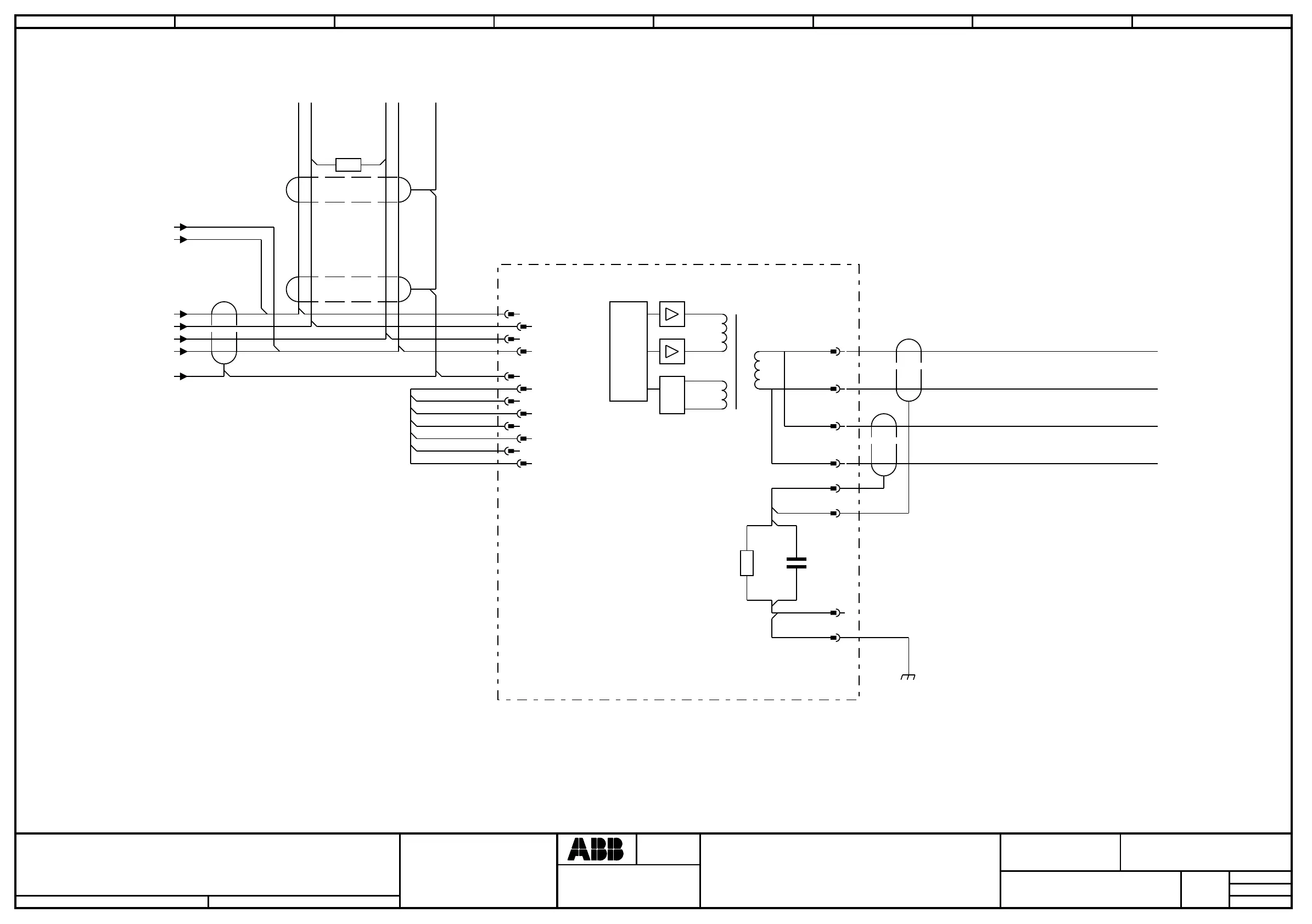
REMOTE I/O UNIT
Location:
Plant:
=
+
+
Sublocation:
EUROMAP
CM.2
Document no.
Next
Rev. Ind
03
Lab/Office:
Status:
Approved
JSUNDIN MTORNROS
2008-07-17
1 2 3 4 5 6 7 8
OR PREVIOUS
I/O UNIT
1) JUMPERS PLACED ACCORDING TO
THE ACTUAL NODE ADDRESS.
2) RESISTANS 120 OHM SHALL ALWAYS
BE CONNECTED IN THE FIRST AND THE
LAST CONNECTOR IN THE CAN-BUS CIRCUIT.
3) CONNECTED IN THE LAST CONNECTOR IN THE
CAN-BUS CIRCUIT.
/13.3 / +24V devicenet
/13.4 / 0V devicenet
/33.5 / V-
/33.5 / CAN_L
/33.5 / CAN_H
/33.5 / V+
/33.5 / DRAIN
3)
120 ohm
12
2)
TO NEXT
I/O UNIT
1)
0V
NA0
NA1
NA2
NA3
NA4
NA5
-X5
1
1
4
4
3
3
7
7
9
9
11
11
2
2
5
5
6
6
8
8
10
10
12
12
NAC
1
1
2
1
2
-X8
11
22
-X9
11
22
33
-X8
33
44
-X9
44
LINE 1 (BLUE)
(BLUE)
LINE 2 (CLEAR)
(CLEAR)
REMOTE I/O IN
REMOTE I/O OUT
I/Ox
REMOTE I/O UNIT