Prepared by, date:
89
We reserve all rights in this document and in the information contained therein.Reproduction, use or
disclosure to third parties without express authority is strictly forbidden. © Copyright 2003 ABB
Page 88
153Total
3HAC024480-004
Latest revision:
Approved by, date:
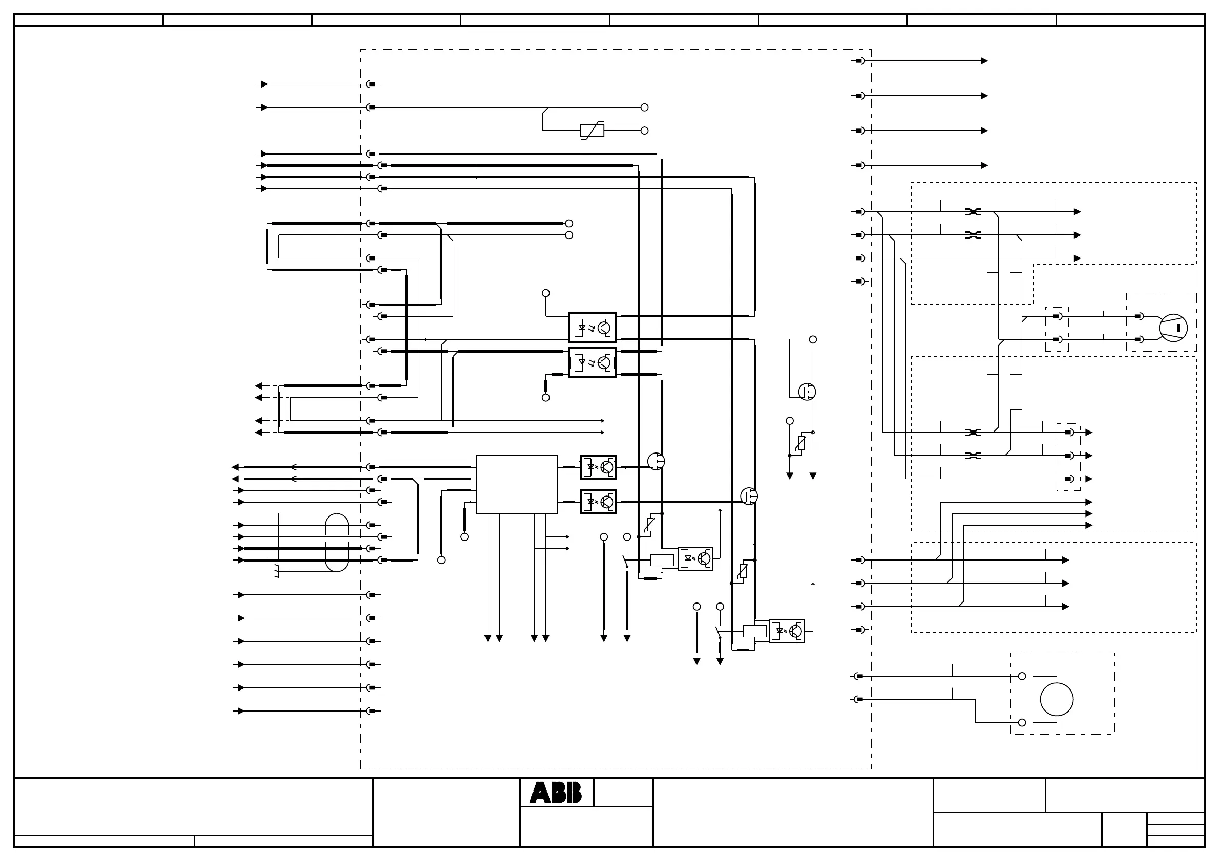
CONTACTOR BOARD
Location:
Plant:
=
+
+
Sublocation:
CAB
DM
Document no.
Next
Rev. Ind
03
Lab/Office:
Status:
CONTROL SYS. IRC5 M2004 DESIGN 06
Approved
2008-07-17
1 2 3 4 5 6 7 8
DRIVE
POWER
SUPPLY
CONTROL
MODULE
A21.X7
LIMIT
OVERRIDE
LIMIT
SWITCH 1
CONTROL
CABLE
CONTROL
MODULE
A21.X7
AXIS
COMPUTER
DRIVE
POWER
SUPPLY
LIMIT
SWITCH 2
EXTERNAL
AXIS
/85.3 /87.3 /86.3 / +24V BRAKE;2
/85.3 /87.2 /86.2 / 0V DRIVE;1
/85.3 /87.1 /86.2 / +24V DRIVE;1
/90.2 / RS485+
/90.2 / RS485-
/90.2 / 0V ENABLE2
/90.2 / ENABLE2
/85.4 /87.4 /86.4 / 0V COOL;1
/85.3 /87.3 /86.3 / +24V BRAKE;1
/85.4 /87.3 /86.4 / 0V BRAKE;2
/85.4 /87.3 /86.3 / 0V BRAKE;1
WHOG
OG
WHBU
BU
LIM2 ch1
LIM2 ch2
LIM1 ch1
LIM1 ch2
LIM2 ch2 ret
LIM2 ch1 ret
LIM1 ch2 ret
LIM1 ch1 ret
-A43
CONTACTOR UNIT
-X6
1
1
2
2
-X1
1
1
3
3
-X22
1
1
4
4
-X23
1
1
4
4
-X21
1
1
4
4
-X1
5
5
7
7
-X4
4
4
7
7
-X7
1
1
3
3
5
5
2
2
4
4
3
3
2
2
3
3
2
2
3
3
2
2
6
6
8
8
5
5
8
8
2
2
4
4
6
6
24VDrive
RunCh1
INTERLOCKING
K2
K1
24VDrive
RunCh2
1 2
LIM2
LIM1
24VDrive
24V
PAN_CH1
CONTINUATION NEXT PAGE
PTC1
PTC1 ret
0V BRAKE
0V BRAKE
PAN_CH2
BRAKE CTRL
-X12
1
1
2
2
-X5
11
22
33
44
-491 AWG20 +24VBU
-492 AWG20
0V
BU
-P1
OPTION :
DUTY
TIME
COUNTER
+
-
h
+
-
/85.4 /87.3 /86.3 / +24V COOL;1
/41.7 / RUN_CH1
/41.7 / RUN_CH1Ret
/41.7 / RUN_CH2
/41.7 / RUN_CH2Ret
/41.7 / ENABLE2_1
/41.7 / ENABLE2_1Ret
/41.7 / SPEED
/41.7 / 0V
PTC1 / /112.3 /132.3 /152.3 /172.2
/122.3 /142.3 /162.3 /202.2
PTC1 ret / /112.3 /132.3 /152.3 /172.2
/122.3 /142.3 /162.3 /202.2
0V BRAKE;3 / /112.3 /132.3 /152.3 /172.2
/122.3 /142.3 /162.3 /202.2
OV BRAKE;4 / /112.3 /132.3 /152.3 /172.2
/122.3 /142.3 /162.3 /202.2
11
-X10
22
33
44
11
-X11
22
33
44
+24V COOL;4 / /178.2
0V COOL;4 / /178.2
FAN1 ret / /178.2
+24V COOL;5 / /178.2
0V COOL;5 / /178.2
FAN2 ret / /178.2
24V COOL
0V COOL
/89.1 / 0V COOL;6
/89.2 / RCH1
/89.2 / 0V COOL;6
/89.3 / RCH2
0V COOL
24V COOL
/89.4 / SELF2
/89.3 / SELF1
/89.4 / LOCK2B
/89.4 / LOCK1A
0V COOL
24V COOL
/89.2 / 0V COOL;6
/89.2 / BRAKE
RunCh1
RunCh2
/142.3 /152.3 /162.3 /92.1.7 / A43-X21:1
/142.3 /152.3 /162.3 /92.1.7 / A43-X21:2
/142.3 /152.3 /162.3 /92.1.7 / A43-X21:3
/142.3 /152.3 /162.3 /92.1.7 / A43-X21:4
1)
1) Jumper if not used
-E4
OPTION :
INTERNAL FAN
1
2
1
2
-380
AWG20 BU
-381
AWG20 BU
-382
AWG20 BU
-383 AWG20 BU
-384 AWG20 BU
-385 AWG20 BU
-386
AWG20 BU
-387
AWG20 BU
-388
AWG20 BU
-389
AWG20 BU
-X1
33
11
M
-A43
-X10.2
11
22
+24V COOL;4 / /177.1
0V COOL;4 / /177.1
FAN1 ret / /177.1
+24V COOL;5 / /177.1
0V COOL;5 / /177.1
FAN2 ret / /177.1
1
2
1
2
-A43
-X10.1
22
11
33
-365
AWG20 BU
-366
AWG20 BU
-731
AWG24 BU
-732
AWG24 BU
-733
AWG24 BU
-734
AWG24 BU
-735
AWG24 BU
-736
AWG24 BU
-737
AWG24 BU
DUAL CABINET
SINGLE CABINET
SINGLE CABINET