2 Installation and Commissioning, IRC5
2.9.9. Installation of cooling fan harness axis 1 and 2
1433HAC021313-001 Revision: K
© Copyright 2004-2008 ABB. All rights reserved.
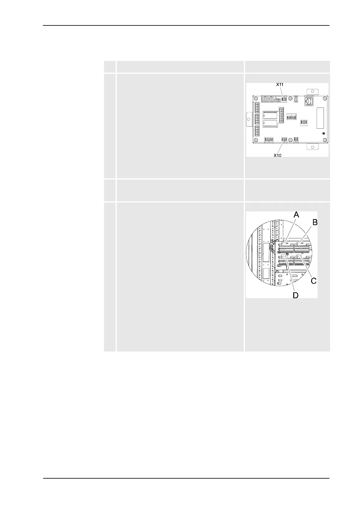
5. Route the cable to the left and connect the harness
connectors to the contactor interface board.
• A43.X11 to X11
• A43.X10 to X10
xx0500002690
See Locations in Single Cabinet
Controller on page 140.
6. Route the wires with terminals to be mounted on the
cabinet door inside the cable protection according to
the illustration.
See Locations in Single Cabinet
Controller on page 140.
7. Fit the snap locking terminals to the plate on the
cabinet door according to the illustration.
xx0600002693
A. XT8/8.1
B. XT8/8.2
C. XP58.2
D. XP58.1
See Locations in Single Cabinet
Controller on page 140.
Action Note/Illustration
Continued