4 Repair activities, controller IRC5
4.3.4. Replacement of customer I/O power supply
1973HAC021313-001 Revision: K
© Copyright 2004-2008 ABB. All rights reserved.
Removal
The procedure below details how to remove the customer I/O power supply.
Standard toolkit The contents are
defined in section
Standard toolkit.
Other tools and procedures
may be required. See
references to these
procedures in the step-by-
step instructions below.
These procedures
include references to
the tools required.
Circuit diagram. 3HAC024480-004
Equipment Spare part no. Art. no. Note
Action Note/Illustration
1.
DANGER!
Before any work inside the cabinet, please observe
the safety information in section DANGER - Make
sure that the main power has been switched off! on
page 28.
2. Remove the Flange disconnect unit (option). Detailed in section Replacement
of Flange disconnect on page 205
3. Loosen the terminal screws for each connected
wire. Remove wires from the terminals.
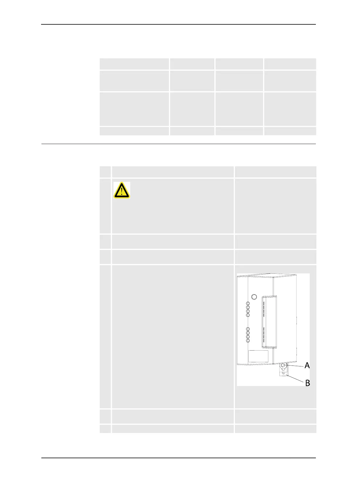
4. Loosen the DIN-lock fixing screw.
xx070000124
• A: DIN-lock fixing screw
• B: DIN-lock lever
5. Pull the DIN-lock lever downwards to release the
power supply unit.
6. Remove the power supply unit.
Continued
Continues on next page