7-4 Surface Map Subsystem
XYZ Panel Orientation (Loaded) 5DX Series 3
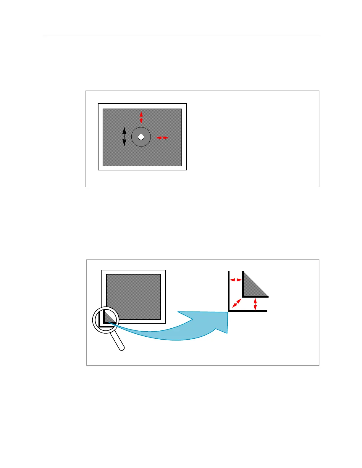
The 5DX System default Field of View (FOV) is (±400 X ±400 mils). The default
FOV is compared with a ±100 mils diameter through-hole solder joint as shown in
Figure 7-1. Tolerance is able to vary without substantially affecting system
accuracy.
Figure 7-1: Field-of-View (FOV) Acceptable Tolerance (Example)
Ideally the overall repeatable accuracy of the system should be within ±25 mils, in
the Open-loop Mode. This 25 mil number is applied to the Snap Margin
parameters as shown in Figure 7-2. The snap margin must also allow for a clear
area around each solder joint. The clear zone is typically 80% of the largest pitch
within the Field of View. The purpose for this clear zone is to permit the proper
analysis of bridging, misalignment, solder balls, and so forth.
Figure 7-2: Snap Margin
X Axis (400 mil)
Y Axis (400 mil)
X positioning ±100 mils
Y positioning ± 87 mils
100 mils
SNAP MARGIN
20 mil gap
DIS
P
LAY REGION
 Loading...

