Agilent 5DX Service Guide 3-5
5DX Series 3 Safety Interlock Controller
For troubleshooting purposes, there are two test points on the Safety Interlock
Controller. TP1 is for Chain 1 and TP2 is for Chain 2. Connect a voltmeter, set to
beep on a voltage level, from the appropriate test point to the test point’s ground. If
an audible voltmeter is unavailable, it will take two persons to troubleshoot the
interlocks, one to check and operate the interlocks and another to monitor voltage
levels.
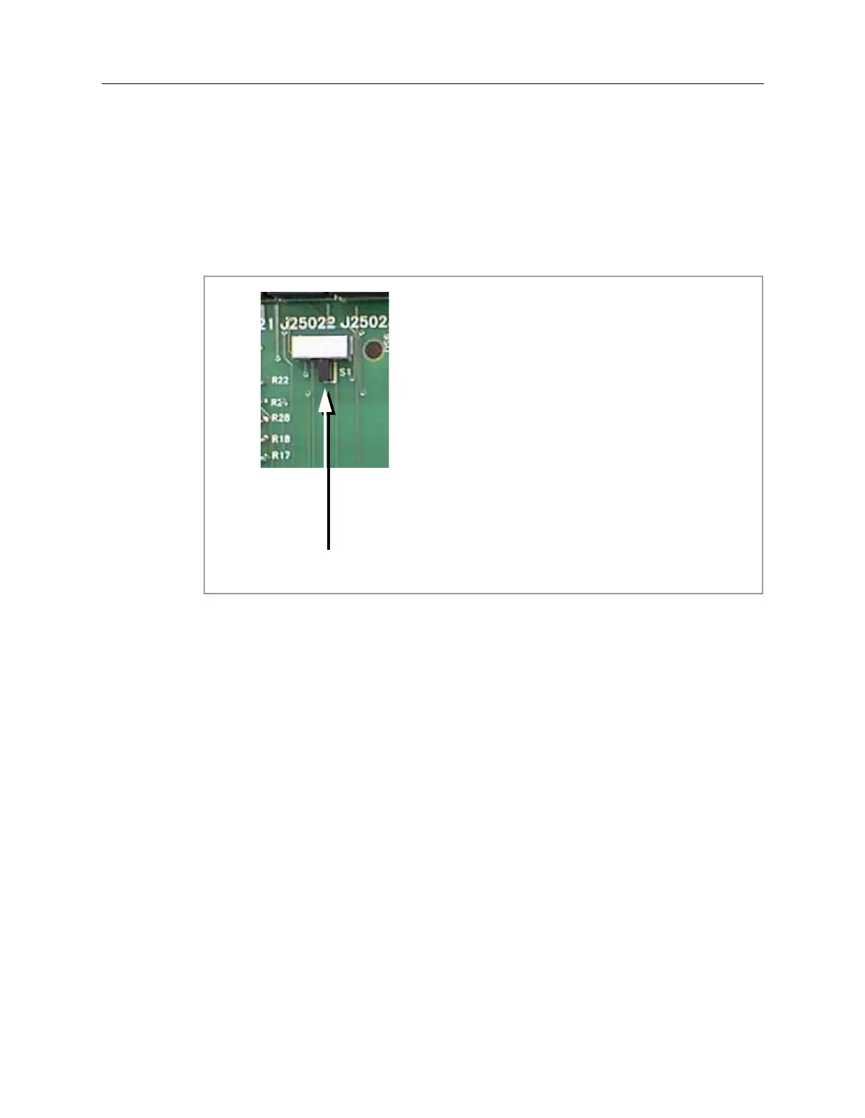
Figure 3-2: Service Switch
Normal
Position
Return the 5DX System to production
status by putting the Service Switch in
the Normal position. The Normal
position is indicated by the white
rectangle on the silkscreen. The switch
in Figure 3-2 is shown in the Normal
position.
 Loading...

