QUICKDESIGNER Allen-Bradley •
••
• 21
CAUTION
Do NOT use this protocol with QP1 devices. It is designed to be used with
ONLY QP2 devices. For example, QPJ-2D100-L2P is a QP2 device.
The SLC 5/03 and SLC 5/04 processors let you operate DF1 communication protocol by means of the
RS-232 communication port, channel 0.
The 9-Pin connector on the SLC 5/03 and SLC 5/04 processors is programmable. The SLC 5/03 and
SLC 5/04 processors can be configured for port-to-port connection using the HMI-CAB-C52 cable.
Channel 0 must be set up for DF1 communication. This configuration can only read/write variables in
the local PLC. Since it is not dependent on network loading, this configuration will provide quick
display updates.
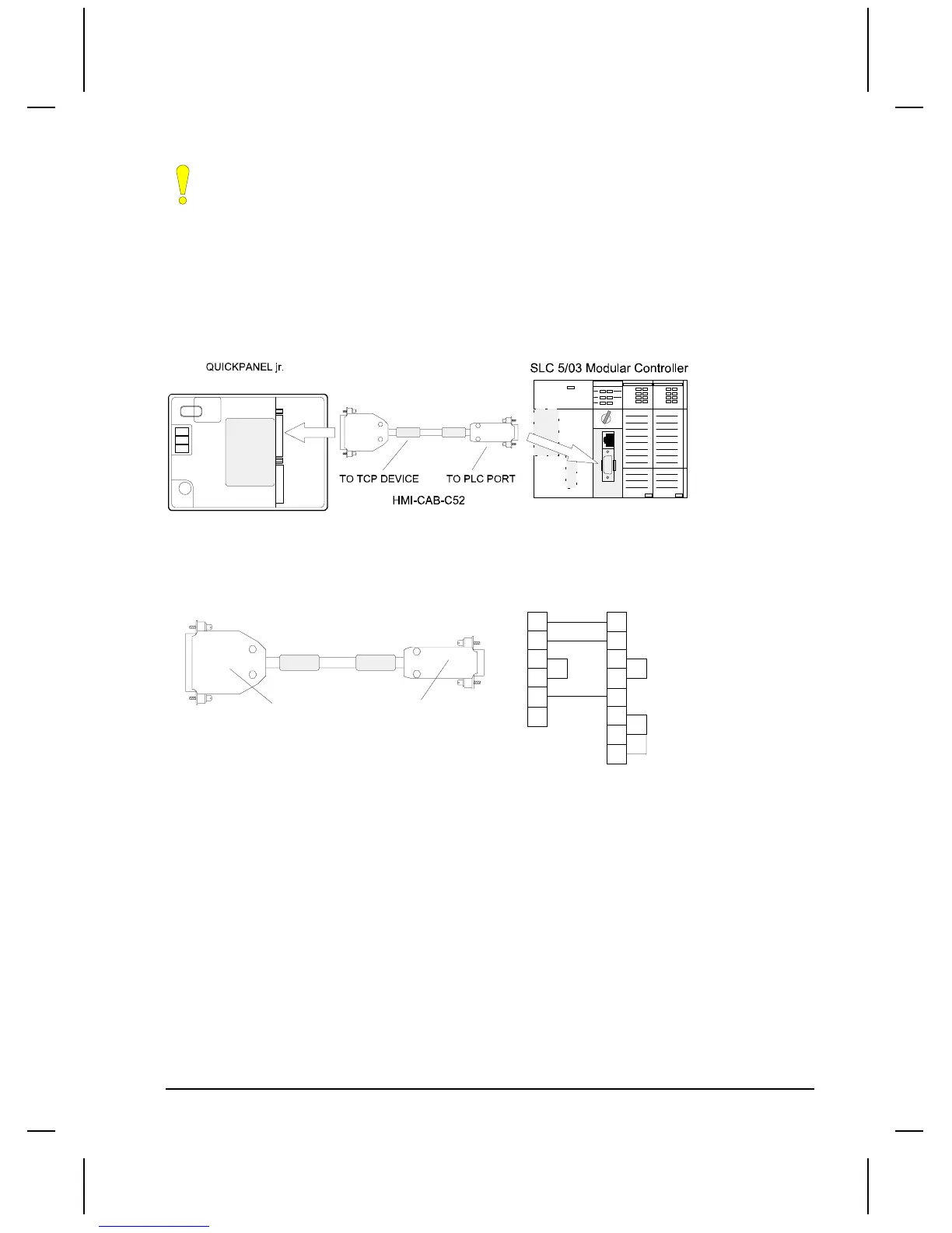
HMI-CAB-C52 Cable
This cable is used to connect the target display to a SLC 5/03 and SLC 5/04 RS232 Channel 0 Port.
Make sure the port is set to DF1 protocol.
TO TCP DEVICE
TO PLC PORT
SHIELD
1
2
3
4
5
7
2
3
4
5
6
8
7
25 PIN MALE
9 PIN FEMALE
HMI-CAB-C52
TO PLC PORT
TO TCP DEVICE
1
Setup for using an A-B SLC 500 DF1
Use the following procedure to ensure your target device is setup properly for the Allen-Bradley SLC
500 DF1. The procedure is in condensed format. Only the required settings are outlined. For additional
details, see Creating a New Project beginning on page 3.

 Loading...


