56 •
••
• Allen-Bradley QUICKDESIGNER
Using Emulate Mode
The rack number is shown in the upper left corner of the dialog box. Use the Previous Rack and Next
Rack buttons located at the bottom of the dialog box to select the rack where you know for certain there
are unused quarter racks.
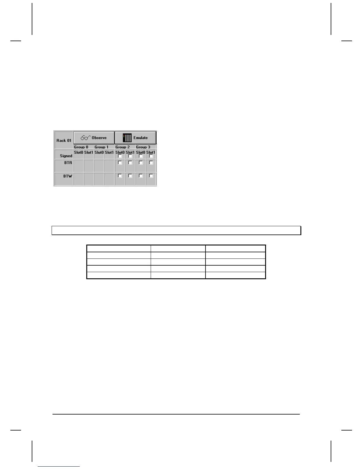
There are four quarter rack sections for each rack displayed. Select which quarter rack you want to
emulate. Click the Observe button to change the quarter rack from Observe mode to Emulate mode. For
this example, the second quarter rack, consisting of Group 2 and Group 3, will be changed to emulate
mode. When the mode changes to emulate, check boxes appear in all slot locations.
Rack Addresses
A rack is the I/O rack number of the I/O chassis in which you placed the target I/O module. For rack
emulation, the target I/O module is the emulated rack. The valid ranges for rack numbers are shown
below.
You cannot do a block transfer to a rack above address 17.
PROCESSOR Maximum Racks Valid Range (octal)
PLC-5/10, -5/12, -5/15 4 00-03
PLC-5/25, -5/30 8 00-07
PLC-5/40, -5/40L 16 00-17
PLC-5/60, -5/60L 24 00-27
Discrete I/O or Block Transfer
At this point, you can decide to use the display device to emulate a rack for discrete I/O only, or go on
to configure the display device to work with Block Transfer read and write operations.
If you want to use Block Transfer Read and Block Transfer Write operations, go to 'Configuring for
Block Transfer Operations' in the next section.
If you do NOT intend on using Block Transfer operations, select all the racks you wish to emulate then
click the OK button to return to the Project Setup dialog box. In this example, the display device will
be configured to emulate the quarter rack addressed as Rack 1, Group 2 and 3. This will allow you to
design panels with discrete I/O. You can have 32 input and 32 output devices on each quarter rack. The
following diagram shows how hardware rack addresses are converted into variable names.

 Loading...


