178 •
••
• PLC Direct QUICKDESIGNER
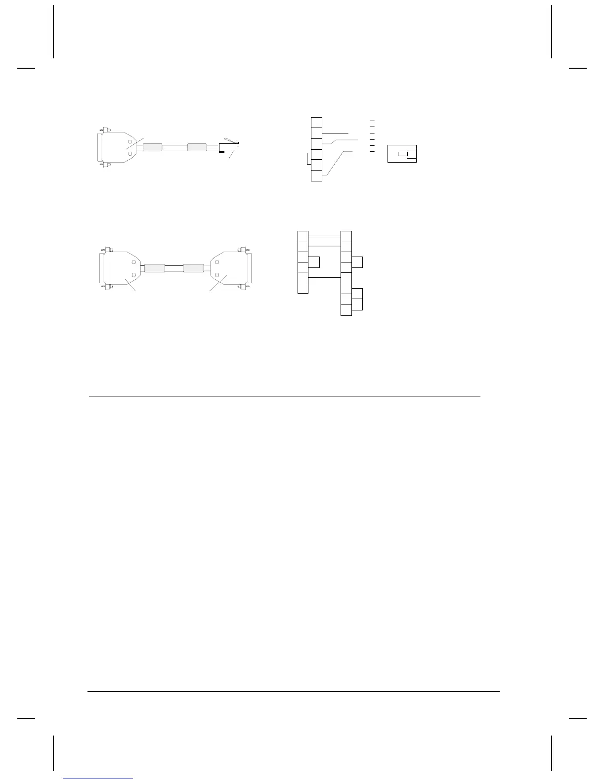
Use the HMI-CAB-C86 Cable for connecting a QuickPanel to a Direct Logic DL350 PORT1.
TO TCP DEVICE
TO KOYO DL240
PROGRAM PORT
25-PIN MALE
6-PIN MODULAR
PHONE
HMI-CAB-C86/B
Modular Phone
red
black
TOP
1
SHIELD
orange
5
4
1
2
3
4
5
6
2
3
7
25-PIN MALE
Use the HMI-CAB-C53 Cable for connecting a QuickPanel to a Direct Logic DL350 PORT2.
HMI-CAB-C53/A
TO TCP DEVICE
TO PLC PORT
SHIELD
1
3
4
5
7
2
3
4
5
7
25 PIN MALE
TO PLC PORTTO TCP DEVICE
2
6
25 PIN MALE
8
20
DL305 Tag Variable Table
Device Address Data Data Data Data Data Bit Read Description
Prefix Range Range Range Format Width Word write / Write & Notes
Min. Max. Order (y/n/rmw)
32 bit types
RD(2) 400-576 -1E+08 1E+08 S (1) 32 norm n/a R/W Variable double
RD(2) 700-776 -1E+08 1E+08 S (1) 32 norm n/a R/W Variable double
RL(2) 400-576 -1E+08 1E+08 S (1) 32 rev. n/a R/W Variable long
RL(2) 700-776 -1E+08 1E+08 S (1) 32 rev. n/a R/W Variable long
RF 400-576 -1E+08 1E+08 D 32 norm n/a R/W Variable float
RF 700-776 -1E+08 1E+08 D 32 norm n/a R/W Variable float
RR 400-576 -1E+08 1E+08 D 32 rev. n/a R/W Variable real
RR 700-776 -1E+08 1E+08 D 32 rev. n/a R/W Variable real
Words
R(2) 400-576 -32768 32767 S (1) 16 n/a ww (3) R/W Variable (BYTE)
R(2) 600-677 0 9999 S (1) 16 n/a ww (3) R/W Counter Acc,Timer Acc
R(2) 700-776 -32768 32767 S (1) 16 n/a ww (3) R/W Variable Byte
Bits
IO 0-157 0 1 n/a 1 n/a ww (3) R/W Input/Output (Bit)
IO 700-767 0 1 n/a 1 n/a ww (3) R/W Input/Output (Bit)
C 160-377 0 1 n/a 1 n/a ww (3) R/W Variable (Bit)
C 770-1077 0 1 n/a 1 n/a ww (3) R/W Variable (Bit)
SR 500-577 0 1 n/a 1 n/a ww (3) R/W Shift Register Bit
CT 600-677 0 1 n/a 16 n/a n R Counter Status
T 600-677 0 1 n/a 16 n/a n R Timer Status
Note: To specify bits for R, use the form Raaa.bb, where aaa means the word address and bb means
the bit specification from 00-15. Writing to bits cause a word write.
Note 1:R location can be interpreted as Signed Integer, Unsigned Integer or BCD. The normal
interpretation of a R location is Signed Integer.

 Loading...


