170 •
••
• OMRON QUICKDESIGNER
SW4 = Transmission format Set to A, which is command level 1, 2, 3, Even parity, 8 data bits, 1 stop
bit.
There are switches located on the back panel, which are viewable by removing the Host Link Module.
Switch 3 is ON, Switch 4 is OFF (factory default). The CTS switch is set to the 0V position (set down
is factory default).
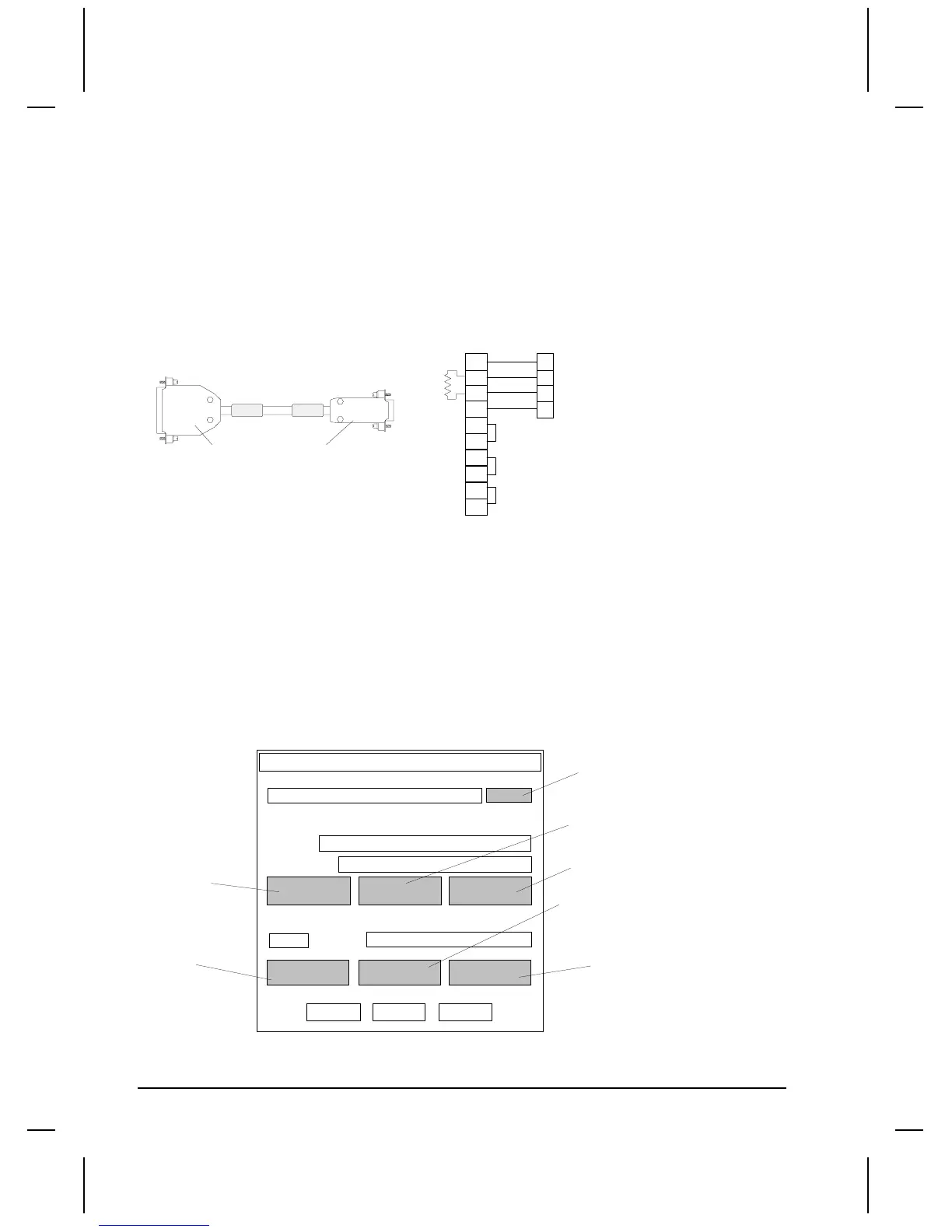
HMI-CAB-C108/A Cable
This cable is used to connect the target display to an Omron C200H LK202 RS422/485
Communications module.
TO PLC PORT
1
5
6
9
25 PIN MALE
HMI-CAB-C108
TO PLC PORTTO TCP DEVICE
9 PIN MALE
16
10
11
15
18
19
21
22
4
5
TO TCP DEVICE
120 OHM
Setup for using an OMRON PLC
Use the following procedure to ensure your target device is setup properly for the Omron PLC. The
procedure is in condensed format. Only the required settings are outlined. For additional details, see
Creating a New Project beginning on page 3.
Project Setup
The drawing is a diagram of the Project Setup dialog box. Each button will display an additional dialog
box. Many settings are options and are not required to establish communications. Verify the Project
name and Display Device Model are correct. Leave the Initial Screen name blank.
Project name:
Display Device
Model
Initial Screen
Display
Touch
Print
More
PLC & Protocols
CN1
PLC Type
PLC Protocol name appears here
Port Protocol System
OK Cancel Help
Project Setup
Default Panel Name
Screen Saver Timeout
Panel Trigger Tag
Watchdog Tag
Watchdog timeout
PLC Protocol setup
Disable Beeper
Electrical Format
Serial Parameters
Project name appears in this field
Model description appears in this field
Project Notes
Print (Inactive)

 Loading...


