QUICKDESIGNER Allen-Bradley •
••
• 45
Configuring dipswitches on the 1770-KF2, Series B Modules
The serial port on the target display is connected to the "Computer Port" on the KF2 module with the
HMI-CAB-C51 cable. The Data Highway port on the KF2 module is connected to the PCL port on a
PLC-5. Each PLC-5 must have a unique station address, which is set with the DIP switches on top of
the PLC-5. The Destination Station Address should be set to match the station address of the PLC that
you will be communicating with the most. The Source Station Address should be set to match the
address set on the KF2 module's dip switches (SW2-SW4).
SWITCH POS STATE COMMENTS
RS422A 1 Open (off) RS422 Communications Disabled
RS232C 2 Closed (on) RS232 Communications Enabled
SWITCH POS STATE COMMENTS
SW1 1 Open (off) Parity = None (Recommended)
SW1 2 Open (off) Disable embedded responses
SW1 3 Open (off) Accept all messages
SW1 4 Open (off) Ignore handshaking signals
SW1 5 Open (off) Use full duplex protocol
Set the Source Station address using switches SW2, SW3 and SW4. SW2 is the most significant octal
digit and SW4 is the least significant octal digit. Valid addresses are from 000 through 377 octal.
SWITCH POS STATE COMMENTS
SW5
SW5
1
2
Closed (on)
Closed (on)
Peer Comm Link Baud Rate. Both switches set
to ON = 57.6 kbps.
SW6
SW6
SW6
1
2
3
Open (off)
Closed (on)
Closed (on)
Computer port baud rate.
As shown = 9600 Baud.
SW6 4 Closed (on) Execute any received diagnostic commands.
SW7
SW7
1
2
Closed (on)
Open (off)
Data Highway to PCL Communication Protocol
Conversion Enabled
Please refer to PLC-2 or PLC-5 sections for valid register names.
Configuring dipswitches on the 1785-KE Series B Module
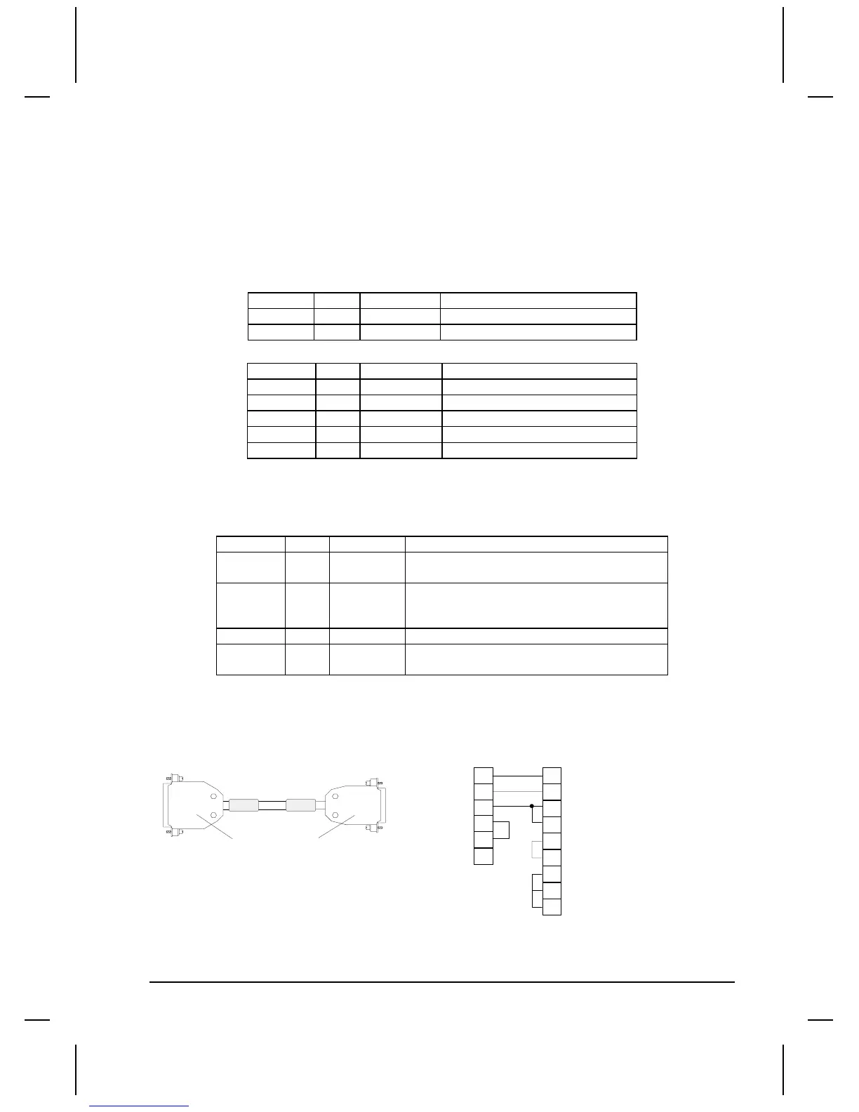
The serial port on the target display is connected to the KE module with the HMI-CAB-C55 cable.
TO A-B KE
DATA HIGHWAY
TO TCP DEVICE
HMI-CAB-C55
TO TCP DEVICE
TO PLC PORT
11
2
8
25 PIN MALE
15 PIN MALE
3
3
7
2
7
1
4
5
4
5
SHIELD
6
13
Set the dipswitches on the KE module as follows:

 Loading...


