QUICKDESIGNER Mitsubishi •
••
• 149
Click OK to return to the Project Setup dialog box.
Setting the Mitsubishi Transmission Control Protocol
The Mitsubishi Computer Interface Module has multiple protocols available by changing the position
of the MODE switch. The target display uses Format 1 which is selected as position 1 for RS232 and
position 5 for RS422.
C
A
B
D
E
F
0
4
1
2
3
5
6
7
8
9
Mitsubishi Serial Communications Parameters
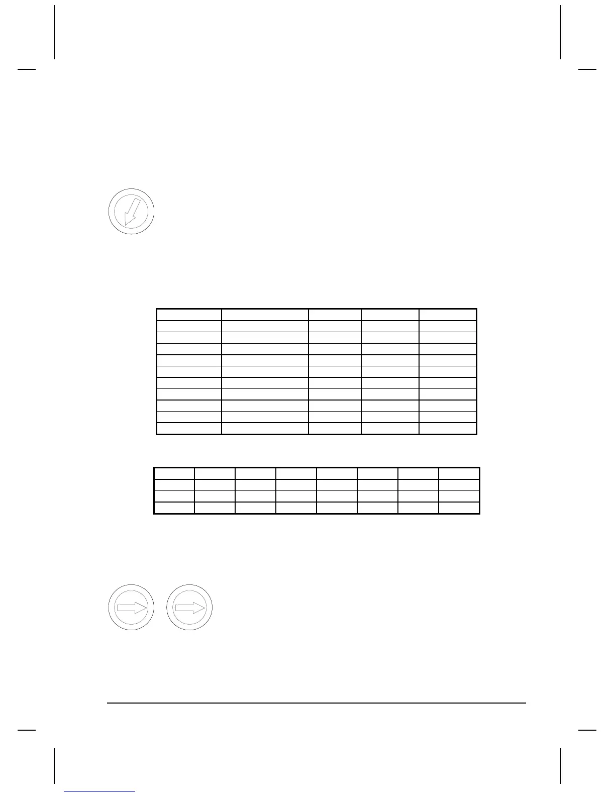
Communication parameters are selected by dip switch settings on the front of the module. Switches are
numbered SW11 to SW24.
SWITCH FUNCTION ON OFF SETTING
SW11 Protocol RS422 RS232C Off
SW12 Data Length 8 bits 7 bits On
SW13,14,15 Baud Rate see table
SW16 Parity Check Yes No Off
SW17 Parity setting Even Odd Off
SW18 Stop bit 2 bits 1 bit Off
SW21 Sum check Yes No On
SW22 Write during run Allowed Disallowed On
SW23 Send Termination Present Absent On
SW24 Rec Termination Present Absent On
Baud Rate Table
300 600 1200 2400 4800 9600 19200
SW13 Off On Off On Off On Off
SW14 Off Off On On Off Off On
SW15 Off Off Off Off On On On
Mitsubishi Station Number
Each Communication Interface Module has a unique station number selected by switches X10 and X1.
The range of station numbers is 0 to 31 decimal.
0
4
1
2
3
5
6
7
8
9
X10
0
4
1
2
3
5
6
7
8
9
X1

 Loading...


