210 •
••
• Siemens QUICKDESIGNER
545-1101 CONFIGURATION
Port 1
RS-232 Port Pinouts
Male 9-Pin D Type
Pin Signal
1 RSD
2 FCV
3 XMT
4 DTR
5 GND
6 DSR
7 RTS
8 CTS
Port 2
RS-422 Port Pinouts
Female 9-Pin D Type
Pin Signal
1 DO+
5 DI+
3 GND
7 DO-
8 DI-
Dipswitch 1 is ON
Port 2
RS-485 Port Pinouts
Female 9-Pin D Type
Pin Signal
1 TX/RX+
7 TX/RX-
3 GND
Dipswitch 1 is OFF
545-1102, 555-110X CONFIGURATION
Port 2
RS-232 Port Pinouts
Male 9-Pin D Type
Pin Signal
2 RCV
3 XMT
5 GND
Port 2
RS-422 Port Pinouts
Female 9-Pin D Type
Pin Signal
3 DO+
9 DI+
5 GND
8 DO-
2 DI-
Dipswitch 1 is ON
Port 2
RS-485 Port Pinouts
Female 9-Pin D Type
Pin Signal
3 TX/RX+
8 TX/RX-
5 GND
Dipswitch 1 is OFFDipswitch 1 is ON
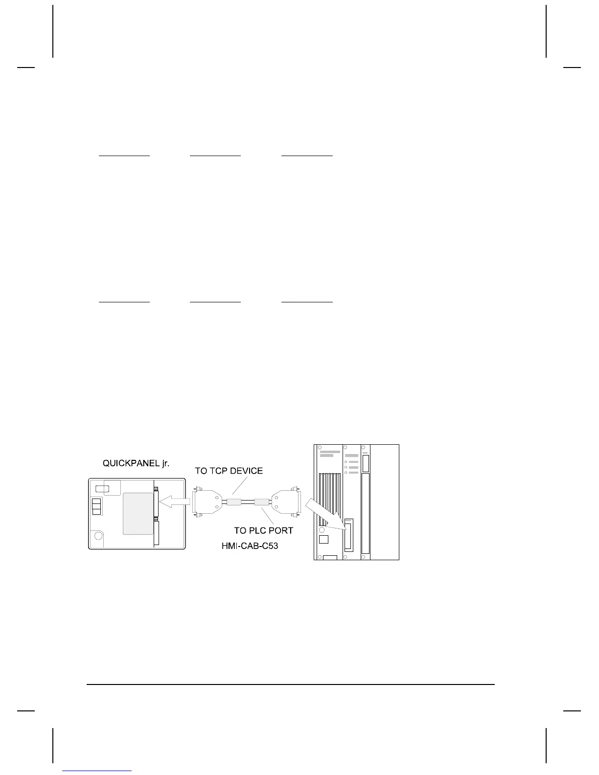
Connecting to Simatic TI 535 Program Port
To connect a target display to a Simatic TI 535 Program Port, use an HMI-CAB-C53 cable as shown in
the following drawing. Make sure you connect the target display to the end marked TO TCP DEVICE
and connect the Simatic TI 535 Program Port to the end marked TO PLC PORT.
The cable drawing and wiring diagram for the HMI-CAB-C53 cable can be found in the Simatic TI
305/405 CCM2 section at the beginning of this chapter.
The target display can also connect to the program port using the cables shown below.

 Loading...


