QUICKDESIGNER GECCM •
••
• 91
GECCM
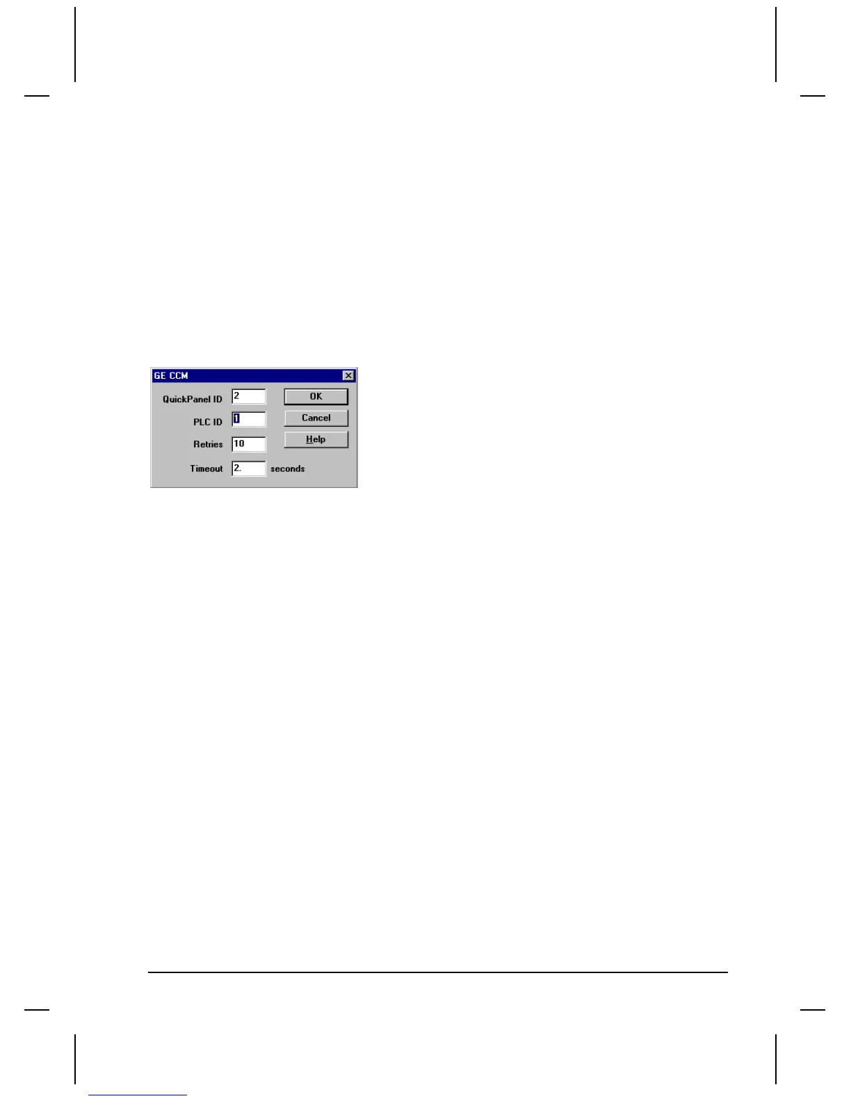
The following picture shows the GE CCM setup dialog box. Enter the QuickPanel ID number and the
PLC ID. The default setting for Timeout and Retries is correct for most applications. Click OK to
return to Project Setup.
Tag Variable Table
Device Prefix Address Range Data Range Data Format Data Width Bit write (y/n/rmw)
Read / Write
32 bit types
RD 1-65535 -99999999 to 99999999 S 32 n/a R/W
RF 1-65535 -2147M to 4294M F 32 n/a R/W
Words
R 1-65535 -32768 to 32767 S(1) 16 y R/W
Note 1
Bits
I 1-1024 0 - 1 n/a 1 y R/W
O 1-1024 0 - 1 n/a 1 y R/W
Note: Address Format for the above tag variables is Decimal.
Note 1: The bit delimiter for R Words is a periord ( . ). The bit range is 0-15 (decimal).
The following are Auxiliary and Channel I/O. This data is mapped to the Register memory. Refer to
the Data Comm User Manual Appendix B for more information.
Device Prefix Channel Range Channel Format Address Delimiter Data Width Bit
write (y/n/rmw) Read / Write
AI n/a n/a n/a 1 y R/W
AO n/a n/a n/a 1 y R/W
I 1-F HEX + 1 y R/W
O 1-F HEX + 1 y R/W
I 0-F HEX - 1 y R/W
O 0-F HEX - 1 y R/W

 Loading...


