QUICKDESIGNER GE GENIUS •
••
• 115
Configuring the Bus Controller for Global Data
The rest of the entries on this screen are used to set up or disable Global Data.
Config Mode: This entry determines how Global Data will be set up for the Bus Controller. If the Bus
Controller will not send or receive Global Data, select NONE. If the Bus Controller will transmit
Global Data, select MANUAL to specify a reference address and data length.
From Addr: Since MANUAL is selected, specify the beginning PLC address from which data
will be transmitted on the bus. It can be from %I, %Q, %G, %R, %AI, or %AQ memory.
Data Length: For MANUAL configuration mode, this entry specifies the amount of Global Data to be
sent each bus scan.
If bit-oriented memory (%I, %Q, or %G) is selected above, this may be 0 to 1024 bits. It must be a
multiple of 8. If you enter a number that is not a multiple of 8, the software will automatically adjust it
upward.
If word-oriented memory (%AI, %AQ, or %R) is selected above, this may be 0 to 64 words. If more
than 64 words are selected, the Logicmaster 90 software automatically adjusts the length to 64 words.
The total amount of memory specified must not exceed the configured memory size for that memory
type. For example, for the 731 CPU, the maximum value for %I memory that can be configured is 512.
To (Opt): This information is not used by the QuickPanel.
After selecting the correct configuration for the Bus Controller, use the ESC key to return to the rack
display.
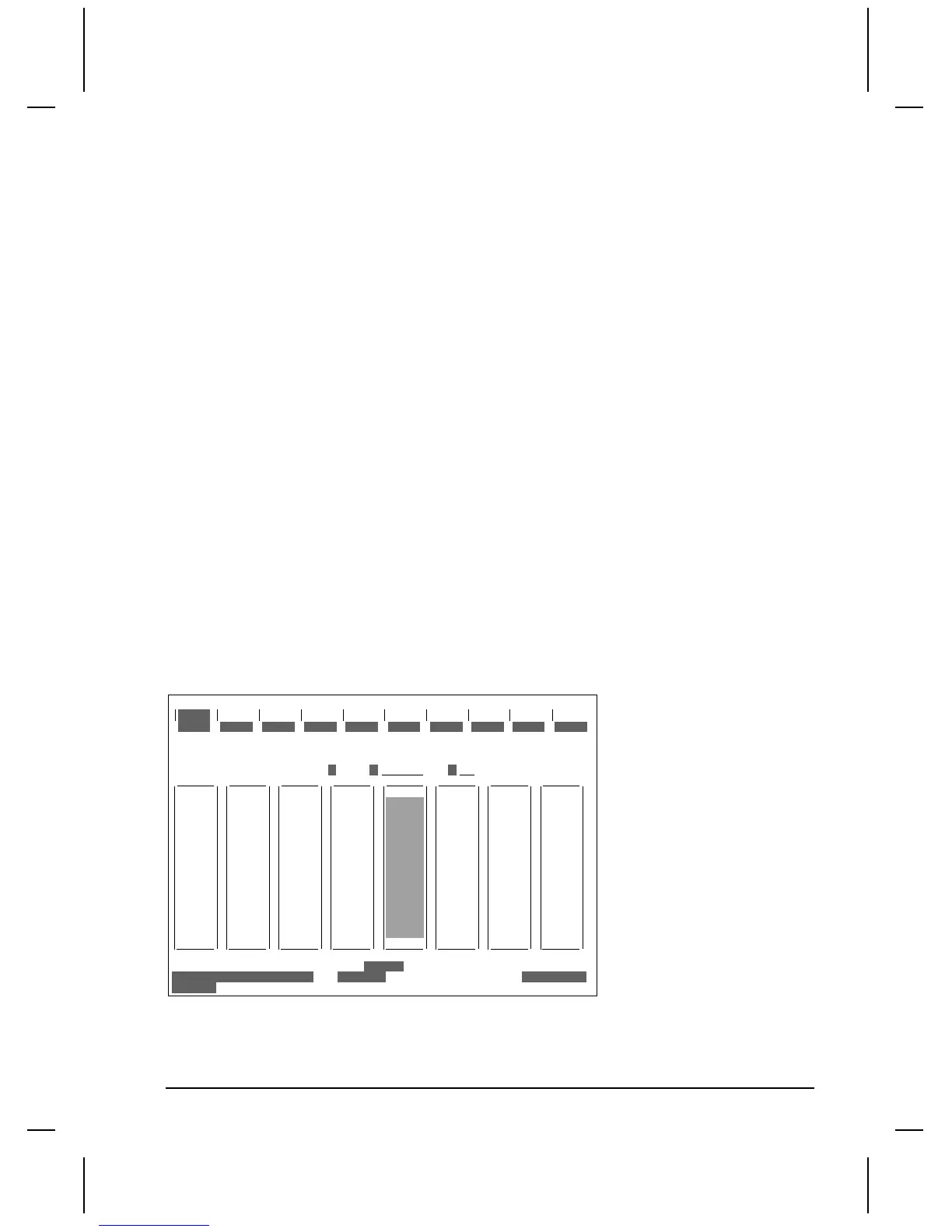
Configuring the QuickPanels on a Bus
After configuring the Bus Controller, the QuickPanels on the bus are configured by placing the cursor
on the Bus Controller in the rack display, then pressing F10 (Zoom).
RACK
1
d in
2
REF VU
3 4 5 6 7 8 9 10
>
RACK
0
BUS ADR
C: \ LM90\ name
REPLACE
OFF LI N E
PRG: name
CONFIG VALID
SLOT
4
BUS
1
d out
COPY
d mix
DELETE
ain
UNDEL
aout amix ot her zoom
24
BUS ADR
25
BUS ADR
26
BUS ADR
27
BUS ADR
29
BUS ADR
28
BUS ADR
30
BUS ADR
31
BEM 731
GBC1
Devices
0
Selecting a Device Number
For all QuickPanels on the bus, the first configuration step is to select the Device Number. Each of the
32 potential locations on the bus is represented by a Device Number from 0 to 31.

 Loading...


