QUICKDESIGNER Allen-Bradley •
••
• 55
Remote I/O Tag Variable Table
Device Address Bit Bit Data Data Data Read Description
Prefix Range delimiter Range Range Range Width / Write & Notes
Min. Max.
Words
I: 0-377 / 0-17 -32768 32767 16 Both Inputs
O: 0-377 / 0-17 -32768 32767 16 Read Outputs
Doubles
AI: 0-376 n/a n/a 0 99999999 32 Both Double Inputs BCD
AO: 0-376 n/a n/a 0 99999999 32 Read Double Outputs BCD
LI: 0-376 n/a n/a -99999999 99999999 32 Both Long Inputs
LO: 0-376 n/a n/a -99999999 99999999 32 Read Long Outputs
ABR@ 0.0-3771.63 n/a n/a 0 99999999 32 Both Double BTR-1
ABW@ 0.0-3771.63 n/a n/a 0 99999999 32 Read Double BTW-1
LBR@ 0.0-3771.63 n/a n/a -99999999 99999999 32 Both Long BTR-1
LBW@ 0.0-3771.63 n/a n/a -99999999 99999999 32 Read Long BTW-1
The device prefix and address delimiter are shown together. Example, AO: where AO is the prefix and : is the
delimiter. Note the delimiter for the BTR and BTW types is the @.
The address syntax is rrgs.oo (rr = rack (octal), g = group, s = slot, oo = offset (decimal))
Double block transfer variables require proper setup of the actual block transfer in the protocol setup.
Emulate Mode
The emulate mode allows the display device to look like an unused rack. The rack assignment is
determined by the unused rack locations existing in your installation.
Make sure you do not try to emulate a rack that already exists on the Remote I/O link.
The target display can handle Block Transfer Reads and Block Transfer Writes. Block transfers allow
you to send and receive large blocks of data over the Remote I/O link.
Emulation is handled in quarter rack increments, with each quarter rack containing two groups (0 and
1), and each group having two slots (0 and 1). Each slot would normally occupy a word in the input or
output image table in the PLC. With Block Transfers, each slot can be assigned up to 64 words of read
and 64 words of write data.
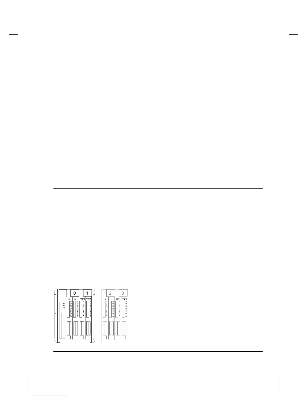
Let's take a look at a fictitious PLC layout and see how the display device can emulate an unused rack.
In the following drawing, a Remote I/O drop occupies only a quarter rack and is addressed as Rack 1.
The rack contains a total of four modules, two in each group. When the display device is in Observe
mode, it can listen to all remote I/O data on the link, including the data sent and received by the scanner
in rack 1.
For this example, there is an unused quarter rack at Rack 1, Group 2 and 3. The display device will
emulate the unused quarter rack.

 Loading...


