200 •
••
• Reliance AutoMate QUICKDESIGNER
Registers and Points
Registers are user accessible 16 bit memory locations within an AutoMate. A Point is a single bit of a
register. Register addresses can range from 0 to 157775 octal, depending on the model of the
AutoMate. Points are the combination of the register address and the bit address within the register.
The bit address can range from 00 to 17 octal.
When looking at a Point number, the User can automatically determine the Register containing that
Point and the individual bit within that Register. For example, the Point 14.15 would be read as register
14 and bit address 15.
Register and Point Ranges
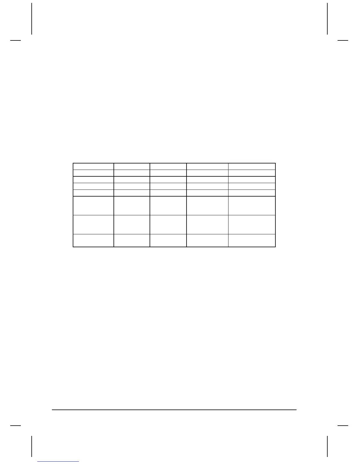
The table below shows the valid register ranges for each of the AutoMate processors. Some of these
registers are reserved for specific functions or data.
Low Point High Point Low Register High Register
AutoMate 15 0.00 15.17 0 15
1000 1067
AutoMate 20 0.00 76.17 0 76
2000 2777
AutoMate
30/30E
0.00
2000.00
20000.00
76.17
3777.17
27777.17
0
2000
20000
76
3777
27777
AutoMate 40 0.00
1600.00
20000.00
177.17
17677.17
157775.17
0
1600
20000
177
17677
157775
AutoMate 40E 0.00
20000.00
17677.17
157775.17
0
20000
17677
157775
Timeout Delay
To complete a transaction, the target display sends a message to read or write data. Messages must be
acknowledged in a specific amount of time. If there is no response to a message, a timeout occurs and
the message is lost. The current timeout delay is shown in seconds. One second is the shortest time
allowed, and any value less than 1 second is treated as 1 second.
Source ID
The Source ID is the target display "RACK" location or the target display ID number. When connected
to the R-Net AutoMate Gateway, this number is also the node number. The target display must act as
an AutoMate Processor in order to communicate, so choose an unused node.
Source Slot
The Source Slot is the target display "SLOT" location. The target display must act as an AutoMate
Processor in order to communicate, so choose an unused slot.
Destination ID
The Destination ID is the default destination rack. This ID is the node that variables are assigned to if
their name lacks the " _ "delimiter.

 Loading...


