60 •
••
• Allen-Bradley QUICKDESIGNER
Block Transfer Operations
In order to read or write block transfer data, your PLC must be programmed to initiate a Block Transfer
Write or Block Transfer Read to an emulated rack address. With a non-continuous block transfer, the
entire block of data is updated each time the processor runs the block transfer instruction. The non-
continuous mode is used to control when or the number of times the block transfer occurs. The
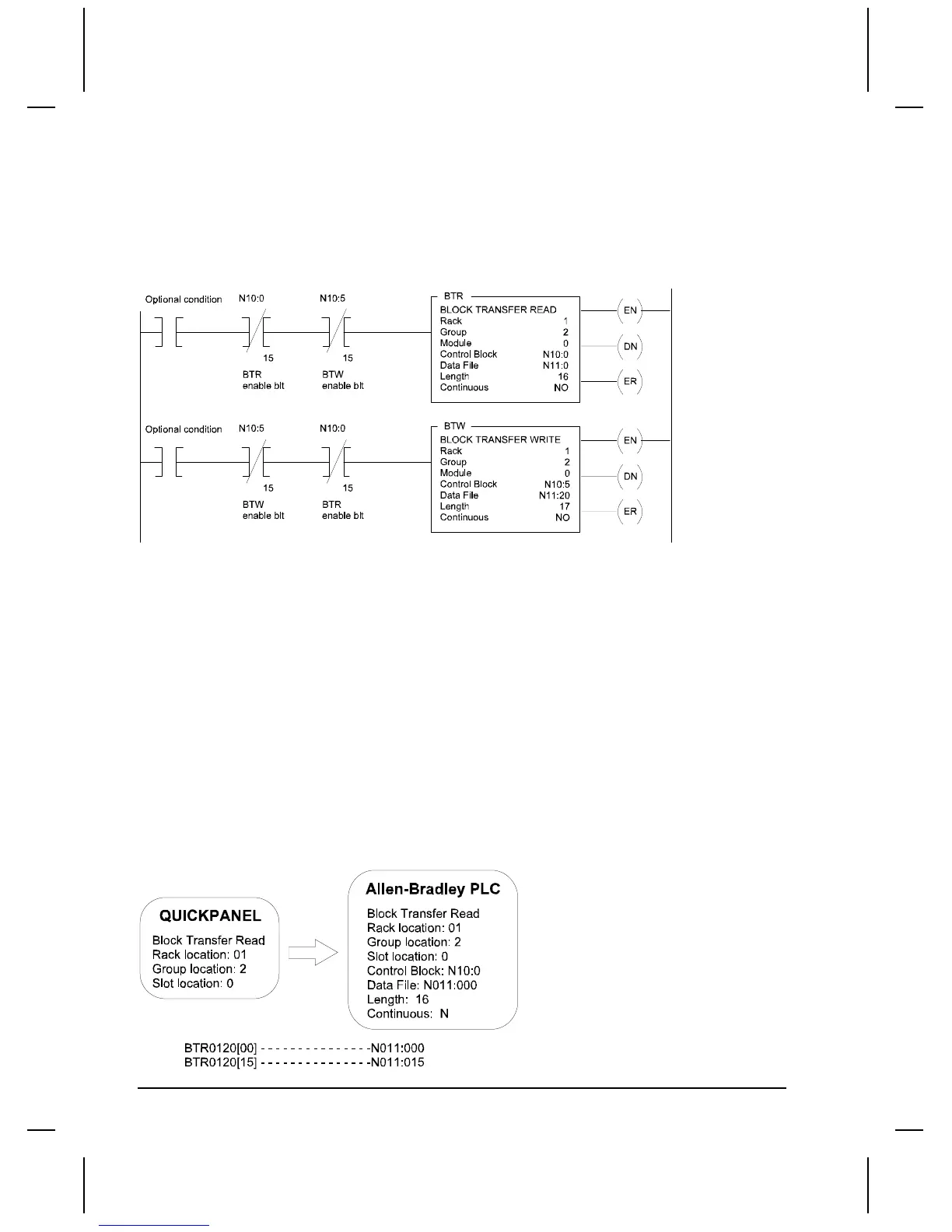
following diagram shows a bi-directional alternating Block Transfer for a PLC-5/VME.
When the rung goes true, the BTW instruction tells the processor to write data stored in the PLC data
file to the specified rack/group/module address. The BTW rack/group/module address is the BTW
emulated address in the target display.
The BTR instruction tells the processor to read data from the rack/group/module address and store it in
the PLC data file. The BTR rack/group/module address is the BTR emulated address in the target
display. The BTR or BTW instruction writes values into its control block address when the instruction
is entered. The processor uses these values to execute the transfer.
Block Transfer Files
In the Using Remote I/O section, you were shown how to assign a Tag Name. Tag names were
automatically selected as BTR0120 and BTW0120. These tag names are used to identify the data files
where the Block transfer information is stored in the target display. Remember that the automatically
assigned tag names also identify the type of block transfer and the rack assignment.
The following drawing shows how a Block Transfer Read function in the PLC reads data from the
BTR0120 file in the target display. Since the Length was set to 16, there will be 16 words read from the
target display into the PLC.

 Loading...


