158 •
••
• Modicon QUICKDESIGNER
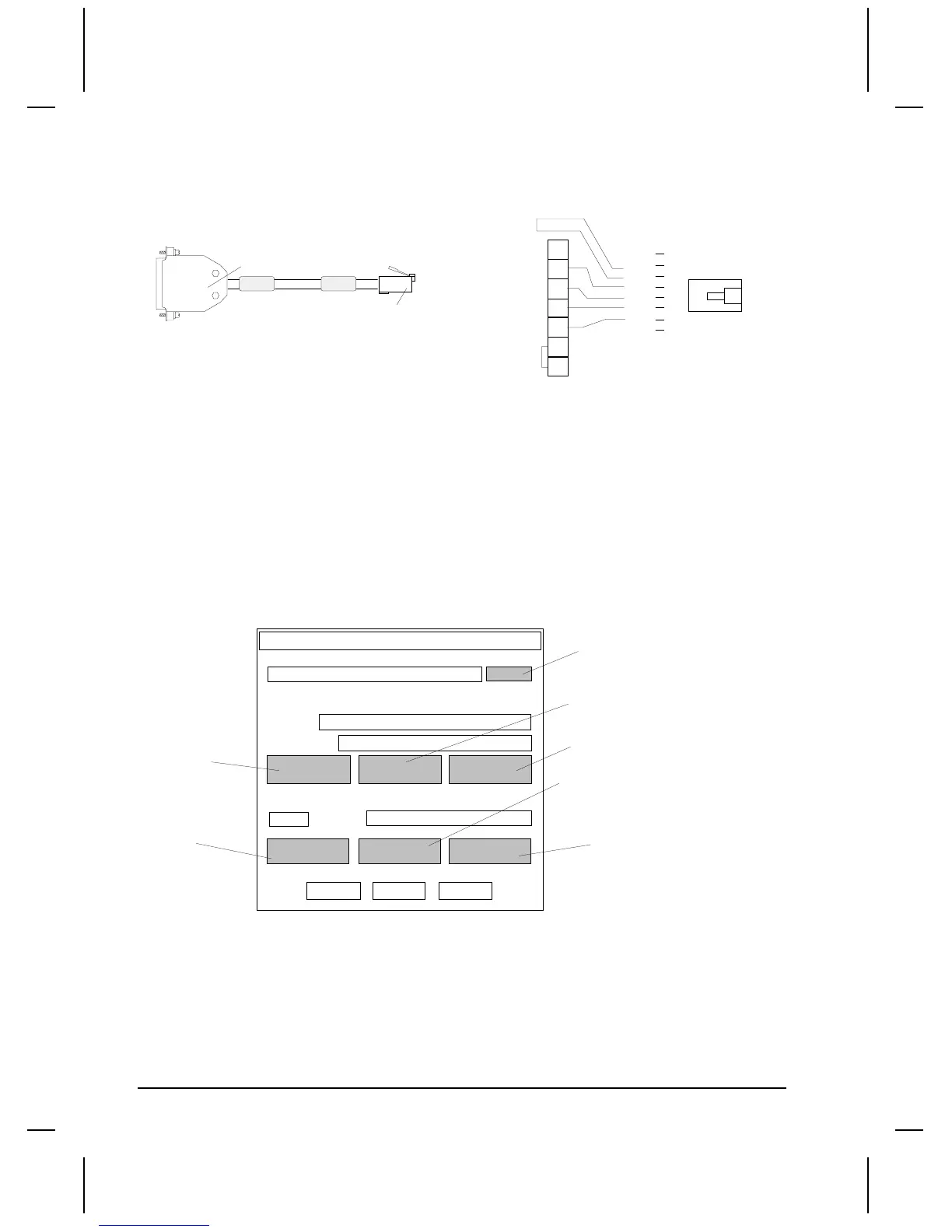
HMI-CAB-C102/A Cable
This cable is used to connect the target display to a Modicon 984 Micro PLC.
TO TCP DEVICE
TO MODICON
MICRO PLC
25-PIN MALE
8-PIN MODULAR
PHONE RJ-45
HMI-CAB-C102/A
RJ-45
TOP
1
SHIELD
2
20
3
7
25-PIN MALE
4
ORG
1
RED
2
WHT
3
GRN
5
BLU
6
BLK
7
BRN
8
SHIELD
4
5
Setup for using an 884 or 984 PLC
Use the following procedure to ensure your target device is setup properly for the Modicon Modbus
PLC. The procedure is in condensed format. Only the required settings are outlined. For additional
details, see Creating a New Project beginning on page 3.
Project Setup
The drawing is a diagram of the Project Setup dialog box. Each button will display an additional dialog
box. Many settings are options and are not required to establish communications. Verify the Project
name and Display Device Model are correct. Leave the Initial Screen name blank.
Project name:
Display Device
Model
Initial Screen
Display
Touch
Print
More
PLC & Protocols
CN1
PLC Type
PLC Protocol name appears here
Port Protocol System
OK Cancel Help
Project Setup
Default Panel Name
Screen Saver Timeout
Panel Trigger Tag
Watchdog Tag
Watchdog timeout
PLC Protocol setup
Disable Beeper
Electrical Format
Serial Parameters
Project name appears in this field
Model description appears in this field
Project Notes
Print (Inactive)
PLC Type
Select the PLC type from the list box. (Modicon Modbus). See PLC Type on page 5.

 Loading...


