QUICKDESIGNER Allen-Bradley •
••
• 23
Protocol Button
Click the Protocol button to display the dialog box associated with the selected PLC.
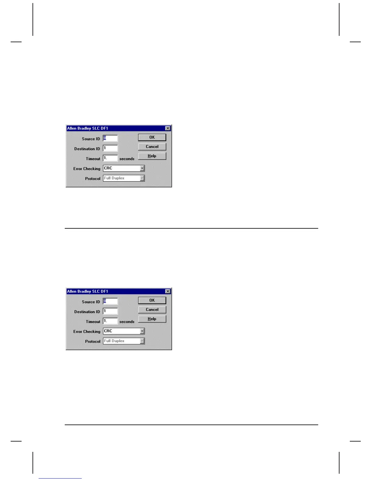
The Source ID is the target display address. The Destination ID is the PLC address where the target
display will get variable data. Enter Timeout in seconds. Select error checking (CRC or BCC) to match
the PLC. Note the Protocol is currently fixed at Full Duplex. Click OK to return to the Project Setup
dialog box.
The drawing shows the setup dialog box for A-B SLC500 DF1.
Tag Variable Table
See the tag variable table on page 19.
Allen-Bradley MicroLogix 1000
The MicroLogix 1000 has an RS-232-C communication port configurable for DF1 protocol for direct
connection to a programming device or operator interface. In this configuration, the MicroLogix 1000
is identical to the SLC500 DF1 protocol. To connect a QuickPanel to a MicroLogix 1000 PLC, use the
SLC 500 DF1 protocol selection and an HMI-CAB-C106 cable.
The drawing shows the setup dialog box for A-B SLC500 DF1.
The Source ID is the target display address. The Destination ID is the PLC address where the target
display will get variable data. Enter Timeout in seconds. Select error checking (CRC or BCC) to match
the PLC. Note the Protocol is currently fixed at Full Duplex. Click OK to return to the Project Setup
dialog box.
Serial Port Parameters
Click the Port button to display the Serial Parameters dialog. The port values are automatically set to
standard default values. The following settings are recommended for AB SLC DF1.

 Loading...


