16 •
••
• Allen-Bradley QUICKDESIGNER
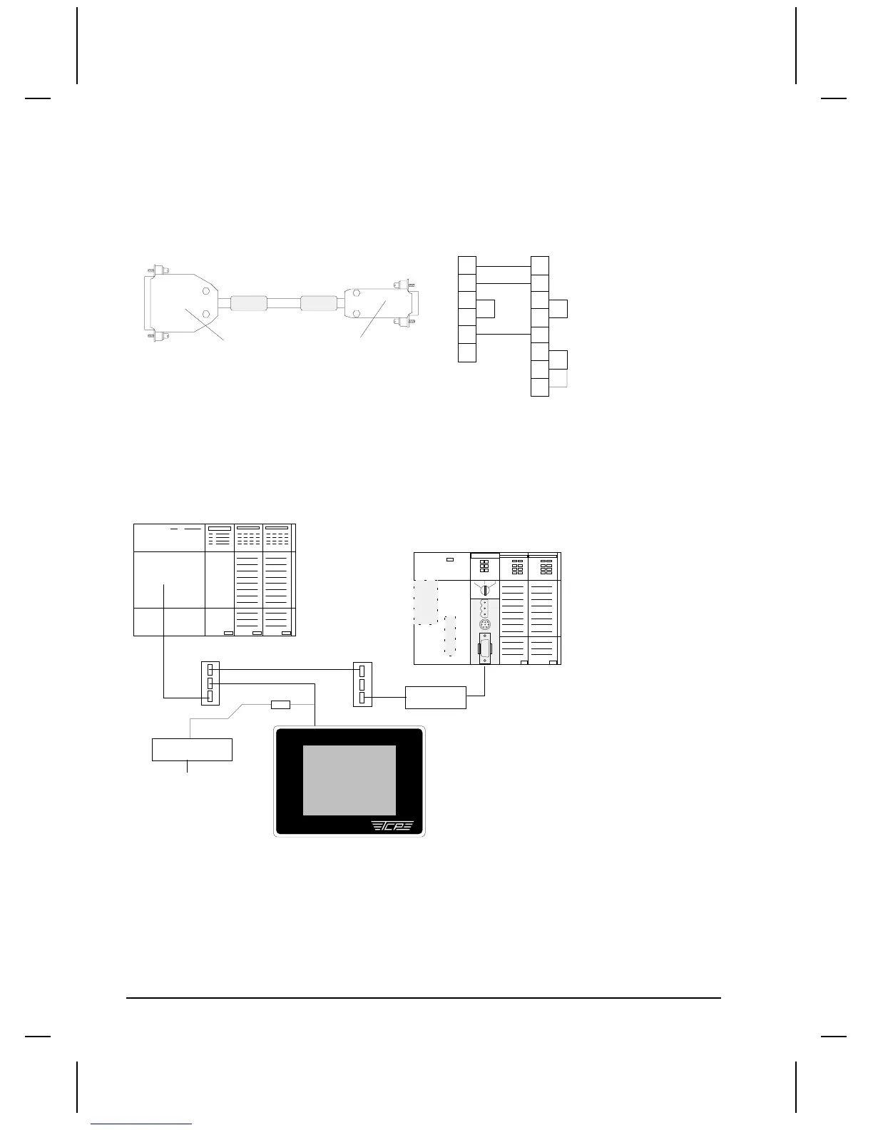
HMI-CAB-C52 Cable
This cable is used to connect the target display to a SLC 5/03 and SLC 5/04 RS232 Channel 0 Port.
A label is placed on each end of the cable to indicate which device should be connected to that end.
One of the labels will also indicate the cable part number so you can quickly verify you are using the
right cable for your application. You can make your own cable using the following wiring diagram.
TO TCP DEVICE
TO PLC PORT
SHIELD
1
2
3
4
5
7
2
3
4
5
6
8
7
25 PIN MALE
9 PIN FEMALE
HMI-CAB-C52
TO PLC PORT
TO TCP DEVICE
1
SLC 5/03 and SLC 5/04 DH485 Connections
You can connect channel 0 of the SLC 5/03 and SLC 5/04 modules to the 1747-PIC to make a
connection to the DH485 network.
SLC 500 5/02 Modular Controller
QUICK PANEL Jr.
1747-AIC Link Coupler
HMI-CAB-C84
1747-PIC
Programming
Station
SLC5/04 Modular Controller
1747-PIC
SLC 5/04 CPU
RUN
FLT
BATT
FORCE
DH+
RS232
RUN REM PROG
Setup for using a SLC 5/03 and SLC 5/04 Channel 0
The procedure for setup of an AB SLC 5/03 Channel 0 is basically the same as for SLC500 DH485.
The Electrical Format must be set to RS232.

 Loading...


