140 •
••
• Interbus-S QUICKDESIGNER
Cables
Cable assemblies, cable and connectors can be obtained from several manufacturers. To avoid
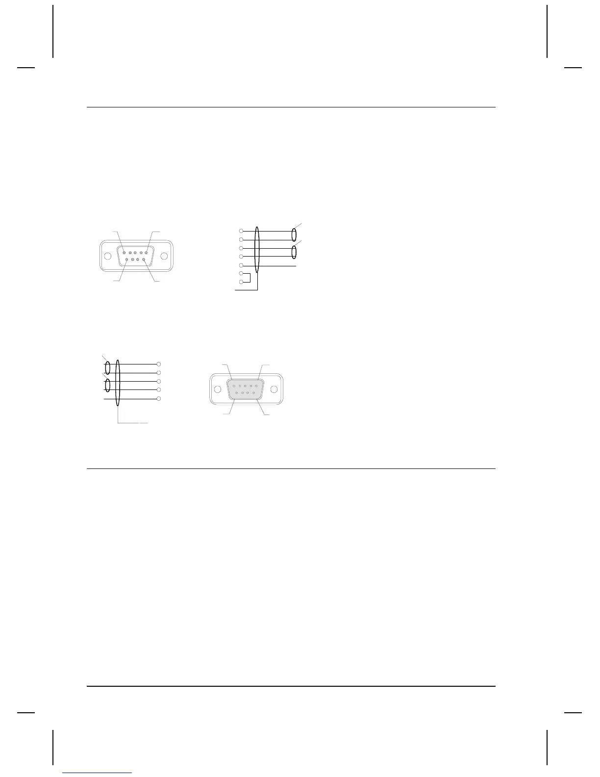
intermittent communications on the network, always connect DO and /DO via the same twisted pair.
Likewise, always connect DI and /DI via the same twisted pair. In addition, always connect both ends
of the cable shielding to their prespective connector housings or shield connection. A connection of 24
volts to data lines will permanently damage the module.
Remote Out
PIN 5 PIN 1
PIN 9 PIN 6
Male D-Sub
Solder Side
DO
/DO
DI
/DI
COM
1
6
2
7
3
5
9
Yellow
Green
Gray
Pink
Brown
Pair
Pair
Connector
Housing
REMOTE OUT
Remote In
PIN 1 PIN 5
PIN 6 PIN 9
Female D-Sub
Solder Side
DO
/DO
DI
/DI
COM
1
6
2
7
3
Yellow
Green
Gray
Pink
Brown
Pair
Connector
Housing
REMOTE IN
Pair
PLC Comm Errors
In the event of a communication problem, error messages are displayed on a status line at the bottom
of the display.
Error Displayed Definition
PLC COMM ERROR (02:FF:A0) Error initializing Anybus module
PLC COMM ERROR (02:FF:01) Incorrect Anybus module ID
PLC COMM ERROR (02:FF:02) Anybus module watchdog time-out (module lockup)
PLC COMM ERROR (02:FF:03) Network Error - Network not connected

 Loading...


