QUICKDESIGNER DeviceNet •
••
• 87
Setup Network
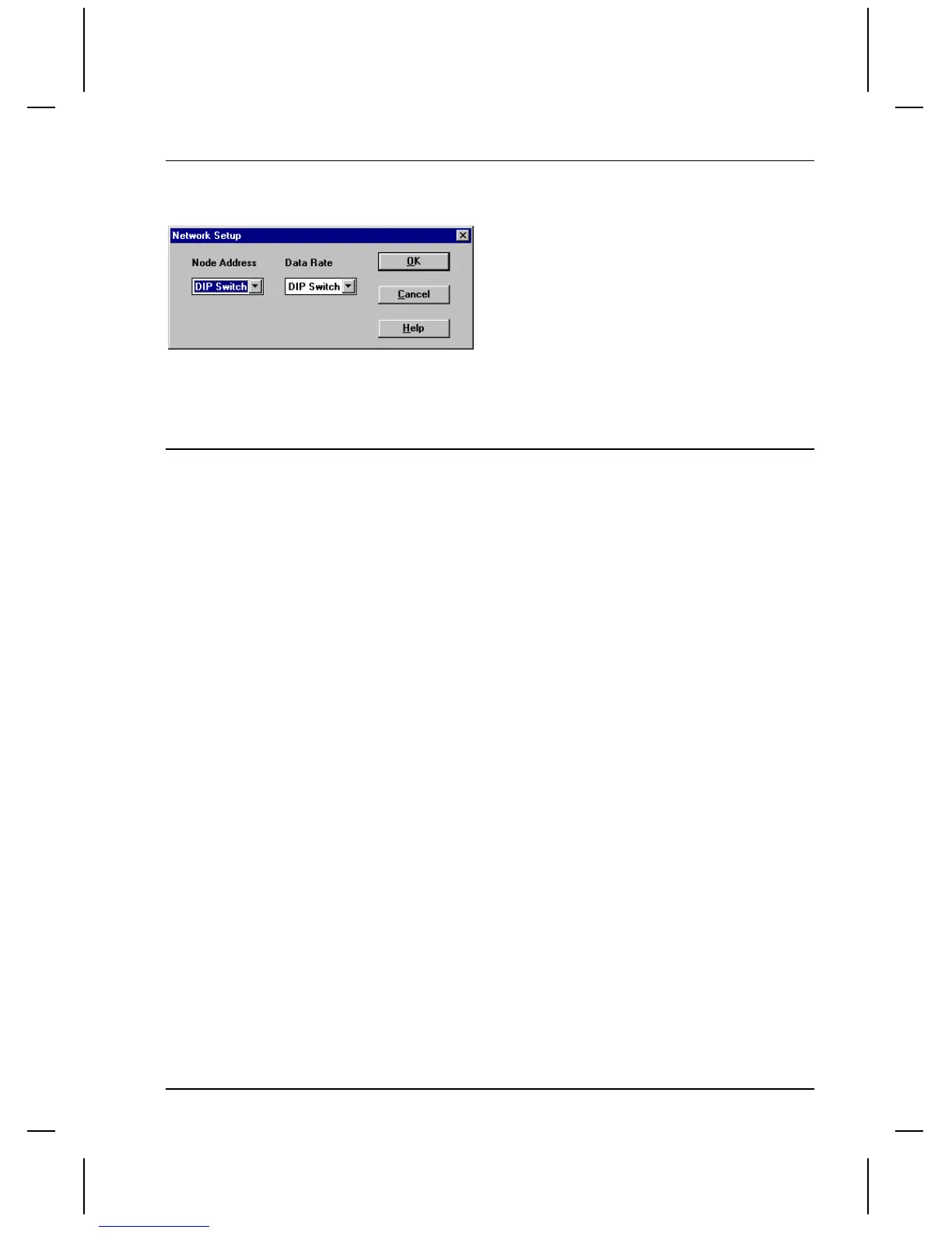
Click the Setup Network button to display the following dialog.
Select the Node Address from the list box. You can choose the DIP Switch on the Device Net module
or an address from the list.
Select the Data Rate from the list box. You can choose to use the DIP Switch on the DeviceNet module
or force the data rate to 125, 250 and 500 Kbaud.
Tag Variables
Valid tag variable names and address ranges are shown in the DeviceNet Protocol dialog box when you
configure the protocol.
The number of Input and Output words and the addressing will determine the valid address range limits
for each variable type. The variable type names are fixed and are displayed in a cell corresponding to
the addressing type.
Byte Addressing Example
Input Words = 127, Output Words = 127, Input start address = 0, Output start address = 0.
Name Address range Value range Write Type
I (Input Bit) I0.0 to I253.7 0 to 1 YBit
Q (Output Bit) Q0.0 to Q253.7 0 to 1 N Bit
IB (Input Byte) IB0 to IB253 0 to 255 Y Byte
QB (Output Byte) QB0 to QB253 0 to 255 N Byte
IW (Input Word) IW0 to IW252 -32768 to 32767 Y Word
QW (Output Word) QW0 to QW252 -32768 to 32767 N Word
ID (2 Word Input) ID0 to ID250 -999999999 to
999999999 Y DWord
QD (2 Word Output) QD0 to QD250 -999999999 to
999999999 N Dword

 Loading...


