Measurement Examples Example 11: Frequency Measurements Using a Separate Source
ML2437A/38A OM/PM PN: 10585-00001 Rev. P 7-33
The response of the device under test is displayed on the screen and the display readout
box on the right-hand side shows:
4. Using the cursors
Two cursors are used to define the points at which or between which power is
measured. They are depicted as vertical dashed lines. The active cursor is depicted in
two ways:
• by a triangular end cap on the end of the dotted line.
• by a hyphen against the cursor number in the display readout box (see
Components of the Profiling Screen).
By positioning the cursors, the display readout box will show the average power
measured between the two cursors.
When Profile mode is first used, both cursors sit at the extreme right hand side of the
display. To move a cursor, press [System]
> [Control].
To move the active cursor, press [<<] or [>>]. To activate the other cursor, press
[SWAP].
To measure the power difference between the cursors, link them first.
Press [System] > [Control] > [-more-] > [-more-] > [LINK CURSR].
If the cursors are now moved using [<<] or [>>], they move as a pair.
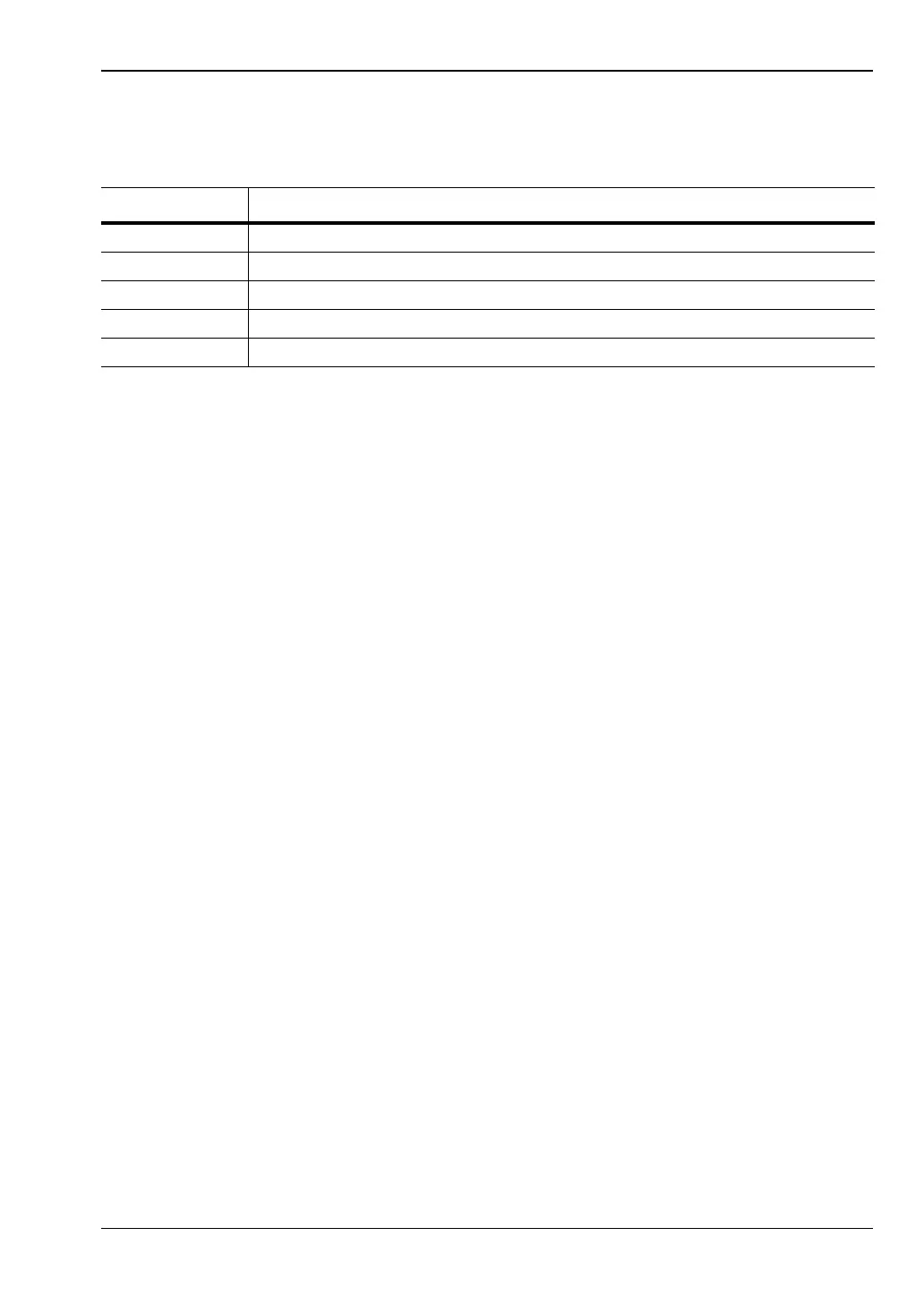
Table 7-6. Display Meanings
Item Meaning
1 the power measurement at cursor 1
2 the power measurement at cursor 2
p the power difference between cursors 1 and 2
x1 the frequency at cursor 1
x2 the frequency at cursor 2