Front Panel Operation Trigger Menu
ML2437A/38A OM/PM PN: 10585-00001 Rev. P 5-19
ARMING [TRGARM GTARM]
Sets the trigger arming, unless the trigger source is set to EXTTTL. When ARMING is
set to Blanking ON, only samples taken when the rear panel Digital Input BNC is
active will be averaged in the measurement. The polarity of the rear panel Digital
Input BNC signal can be set (high or low) using the System > Rear Panel > BNC > TTL
LEVEL menu setting.
When ARMING is set to Blanking OFF, all samples are read irrespective of the level on this
BNC.
1. Connect to the rear panel digital input.
2. Select Trigger > Setup > ARMING > Blanking ON.
3. Set the polarity of the blanking (System menu)
Example power meter reading: –9.16 dBm.
TYPE [TRGTYP GTTYP]
The Type selection (RISE or FALL) sets the trigger for a rising or falling edge. When
the trigger source is set to INTA or INTB (Internal A or B) the power meter triggers on
a power level which is rising or falling.
LEVEL [TRGLVL GTLVL]
The Level selection sets the internal trigger level. When the trigger source is set to
either INTA or INTB (internal sensor A or B) the channel triggers on a power level (in
dBm) given by the sensor. This value must not take any cal factors or offsets that the
meter applies into account.
Note
Use Arming to synchronize to other equipment or modulation/burst
synchronization. This is a simple way to inhibit measurements during user-defined
periods without entering actual time periods.
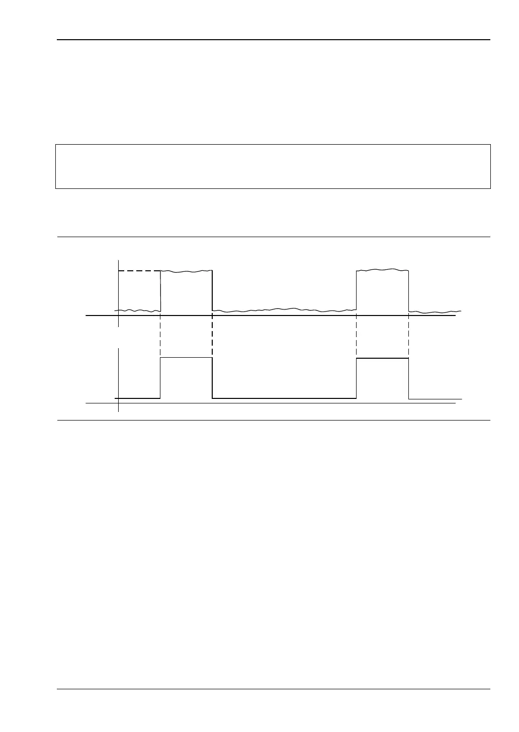
Figure 5-3. Typical Arming Diagram
-9
dBm
-50
TTL
GSM BURST
FROM GENERATOR
BURST TRIGGER SYNC
FROM GENERATOR