Trigger Menu Front Panel Operation
5-20 PN: 10585-00001 Rev. P ML2437A/38A OM/PM
Trig 1
If Trigger Channel 1 SOURCE is set to Manual, this softkey initiates a measurement
for channel 1.
Trig 2
If Trigger Channel 2 SOURCE is set to Manual, this softkey initiates a measurement
for channel 2.
Trig 1&2
If Trigger Channels 1 and 2 SOURCE are set to Manual, this softkey triggers both
channels simultaneously.
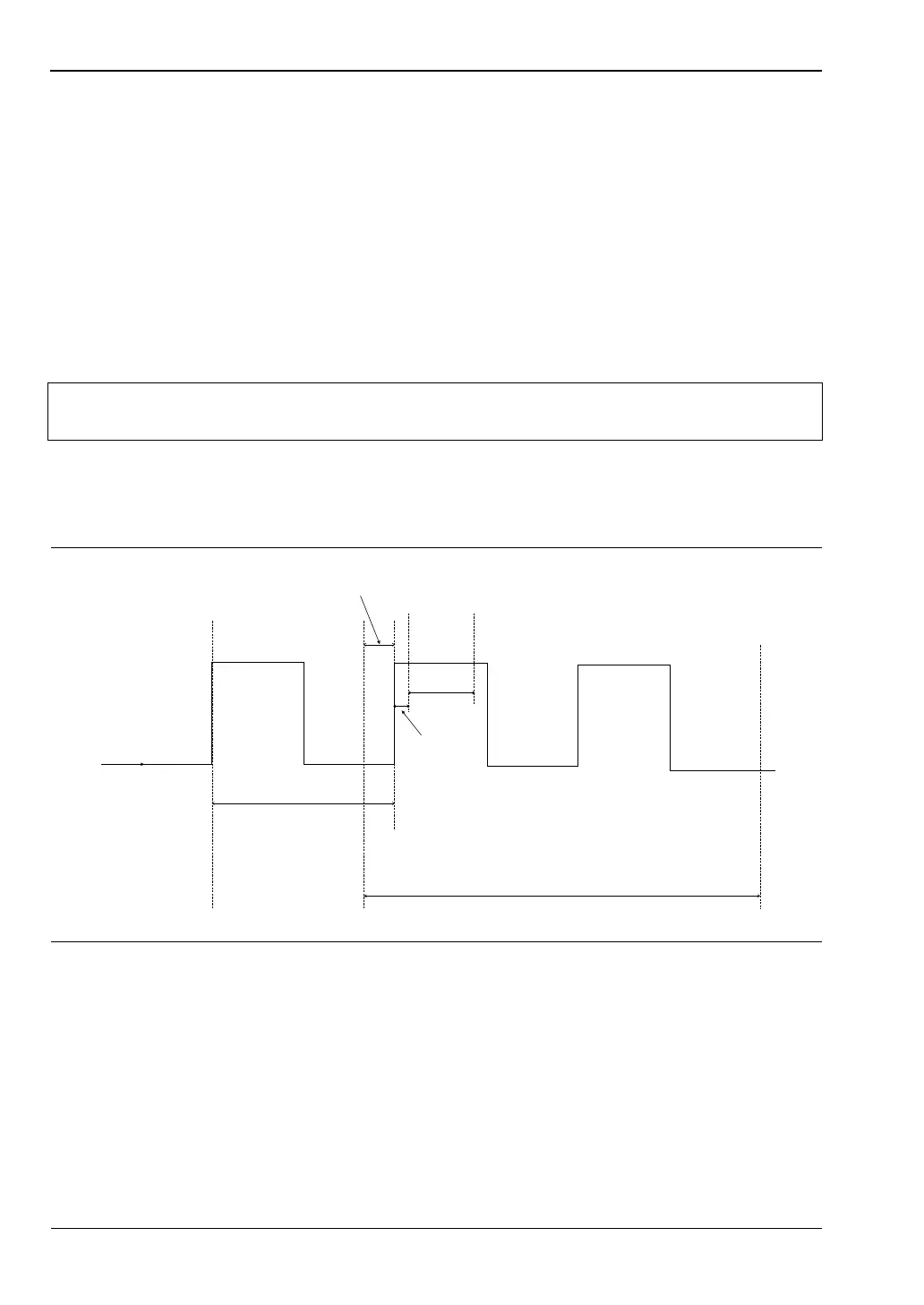
The following figure shows a typical trigger timing diagram. Note that the display
trigger delay is only present when in Profile operation mode, and helps in setting the
‘window’ position along the signal.
The Data Collection Time (collection period) is only present when in Profile operation
mode (System > Profile > PERIOD), and is the period of time displayed on the profile
graph.
The Gate Width is the section of the signal in which the measurements are performed.
In Profile mode, this is the time between Cursor 1 and Cursor 2 and is used to provide
the Between Cursor Average measurement.
Display Trigger Delay (System > Profile > DELAY) is the delay after the trigger point.
Note
The effective range is approximately -30 dBm and is only active in DC ranges 1
and 2.
Figure 5-4. Sample Trigger in Graphic Mode
INCOMING SIGNAL
FROM SENSOR
TRIGGER POINT
DATA COLLECTION TIME
(PROFILE MODE)
DISPLAY TRIGGER DELAY
(PROFILE MODE)
GATE
WIDTH
DELAY
PRETRIGGER % CURSOR
1
CURSOR
2