Programmer’s Model
ARM DDI 0210C Copyright © 2001, 2004 ARM Limited. All rights reserved. 2-11
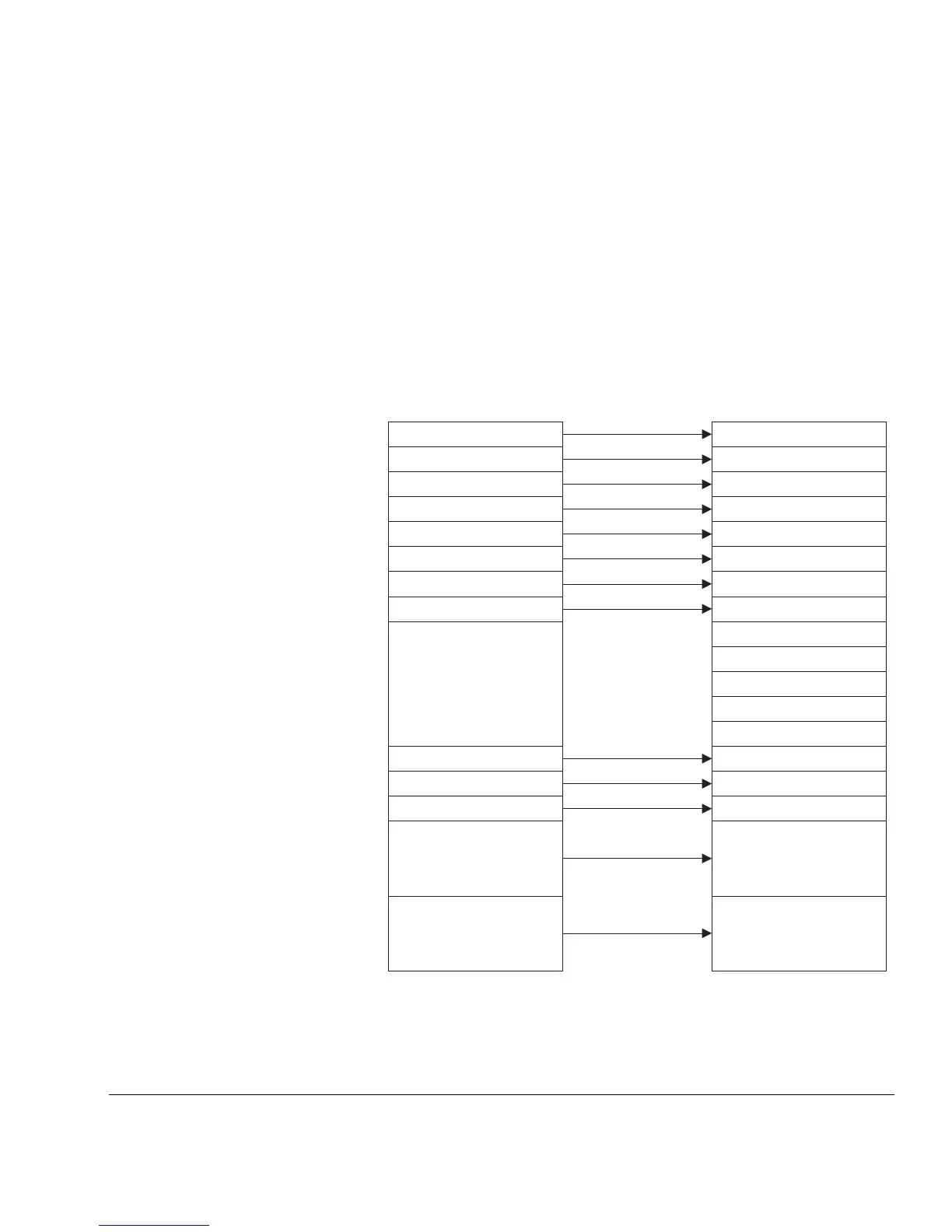
2.6.3 The relationship between ARM-state and Thumb-state registers
The Thumb-state registers relate to the ARM-state registers in the following way:
• Thumb-state r0–r7 and ARM-state r0–r7 are identical
• Thumb-state CPSR and SPSRs and ARM-state CPSR and SPSRs are identical
• Thumb-state SP maps onto the ARM-state r13
• Thumb-state LR maps onto the ARM-state r14
• Thumb-state pc maps onto the ARM-state pc (r15).
These relationships are shown in Figure 2-5.
Figure 2-5 Mapping of Thumb-state registers onto ARM-state registers
Program counter (PC)
r1
r2
r3
r4
r5
Thumb state
r6
r7
Stack pointer (SP)
Link register (LR)
Current program
status register
(CPSR)
Saved program status
register (SPSR)
PC (r15)
r1
r2
r3
r4
r5
ARM state
r6
r7
r8
Stack pointer (r13)
Link register (r14)
CPSR
SPSR
r9
r10
r11
r12
r0 r0