AC and DC Parameters
7-6 Copyright © 2001, 2004 ARM Limited. All rights reserved. ARM DDI 0210C
The timing parameters used in Figure 7-3 on page 7-5 are listed in Table 7-3.
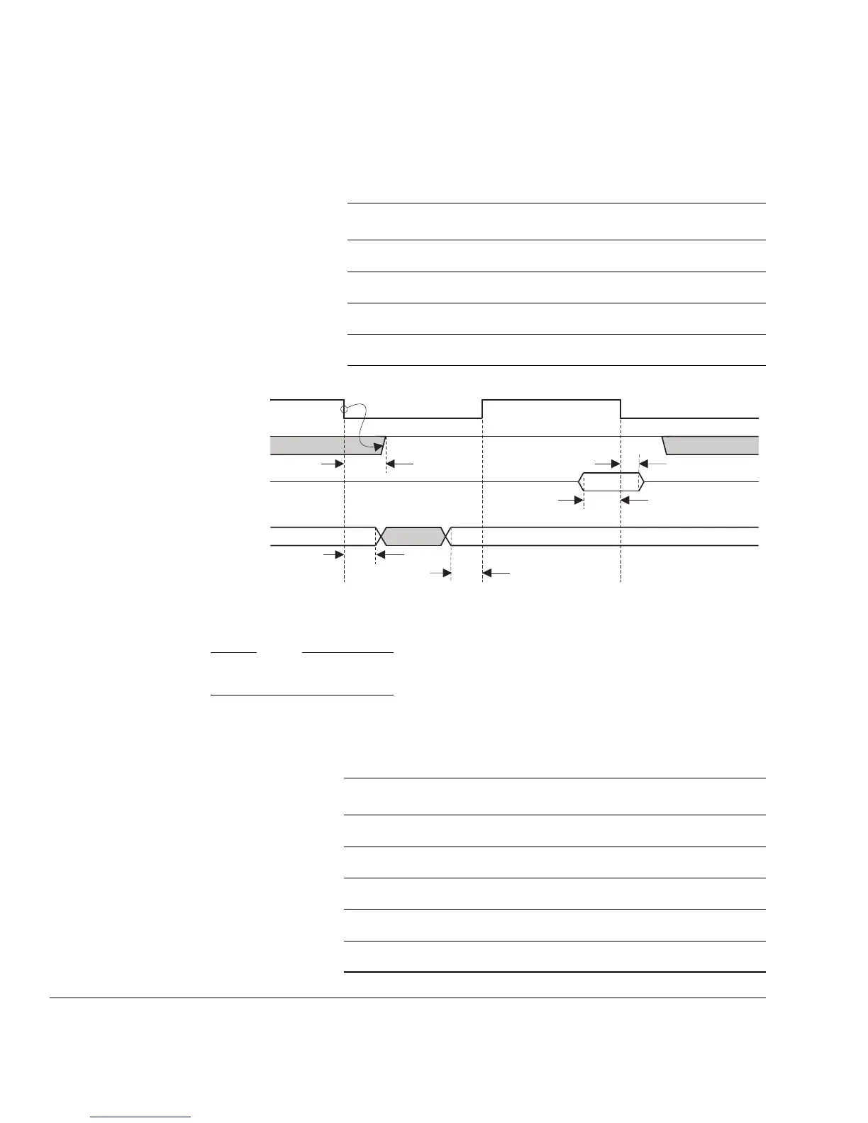
Figure 7-4 Bidirectional data read cycle
Note
In Figure 7-4, DBE is HIGH and nENIN is LOW during the cycle shown.
The timing parameters used in Figure 7-4 are listed in Table 7-4.
Table 7-3 Bidirectional data write cycle timing parameters
Symbol Parameter Parameter type
T
doh
DOUT[31:0] hold from MCLKfMinimum
T
dout
MCLKf to D[31:0] valid Maximum
T
nen
MCLKf to nENOUT valid Maximum
T
nenh
nENOUT hold time from MCLKfMinimum
MCLK
nENOUT
D[31:0]
T
nen
T
dis
BL[3:0]
T
bylh
T
byls
T
dih
Table 7-4 Bidirectional data read cycle timing parameters
Symbol Parameter Parameter type
T
bylh
BL[3:0] hold time from MCLKfMinimum
T
byls
BL[3:0] set up to from MCLKrMinimum
T
dih
DIN[31:0] hold time from MCLKfMinimum
T
dis
DIN[31:0] setup time to MCLKfMinimum
T
nen
MCLKf to nENOUT valid Maximum