KVM over IP Matrix System User Manual
88
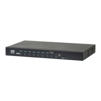
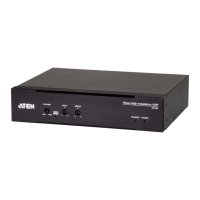
KE6900A / KE6940A Point-to-Point Installation
Setting up the KE6900A / KE6940A system in a point-to-point configuration
is simply a matter of plugging in the cables.
Note: In a point-to-point configuration, no administrator setup is required.
Make sure that all equipment is powered off. Refer to the installation diagrams
on the next two pages and do the following:
1. (Optional) Connect a grounding wire between the extender’s grounding
terminal and a suitable grounded object.
2. On the transmitter side, plug the mouse, keyboard, DVI monitor, and serial
devices into the ports on the console section of the transmitter
(KE6900AT/KE6940AT)
1
.
3. Connect the DVI-D cable and the USB 2.0 Type-A to Type-B cable
provided with this package into the KVM ports on the front of the
transmitter.
4. Connect the other end of the USB DVI-D KVM cable into the keyboard,
video, mouse, speaker, and microphone ports on the computer.
5. For control of serial devices, connect the RS-232 port on the front of the
transmitter to a serial port on the computer.
6. Connect a Cat 5e/6 cable to the transmitter’s LAN port.
7. Plug the mouse, keyboard, DVI monitor, and serial devices into the ports
on the console section of the receiver (KE6900AR/KE6940AR)
2
.
8. Connect the other end of the Cat 5e/6 cable to the receiver's LAN port.
9. Instead of connecting through the LAN ports, you can choose to connect
the extenders through the SFP slots. To do so, plug SFP modules into the
transmitter and receiver’s SFP slots, then connect each end of Gigabit
Ethernet (GbE) optical fiber between the SFP modules
3
.
10. Plug the power adapters into AC sources with the power cords and plug
the other ends into the transmitter and receiver’s power jacks respectively.
11. (Optional) For power redundancy, plug the second power adapters into AC
sources with the power cords and plug the other ends into the transmitter
and receiver’s power jacks.
12. Power on the computer.
 Loading...