Chapter 1. Introduction
13
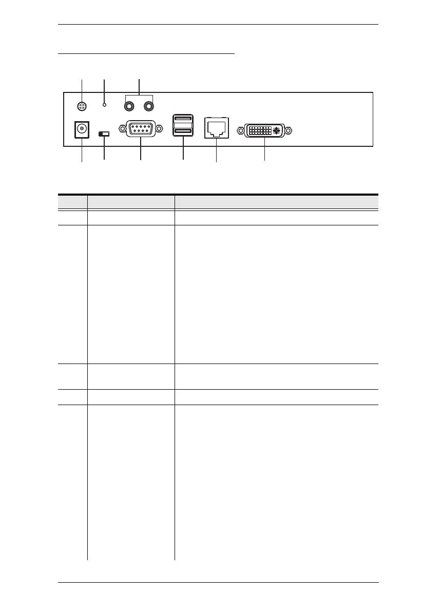
KE6900T (Transmitter) Rear View
No. Component Description
1 grounding terminal The wire used to ground the unit connects here.
2 reset button This button must be pushed with a thin object, such as
the end of a paper clip.
Press and release to reboot the device.
Power off, hold reset then power on the device
while pressing reset to recover from a firmware
upgrade failure.
Press and hold it in for more then three seconds
resets the unit back to its factory default
settings*.
Note: The Reset to Factory Default function resets everything
but the login information (username/password) to the factory
default settings. To reset the login information, refer to Reset
All Information on page 423.
3 audio ports These mini stereo ports are for the speakers (green)
and microphone (pink).
4 power jack The cable from the DC power adapter connects here.
5 function switch Use this slide switch to set the unit’s mode to:
Auto: Shared (simultaneous) KVM control of the
computer at the Transmitter and Receiver console.*
RS-232 Config: The device is ready to be
configured via serial commands through the RS-232
port. When connected to a KVM over IP Access
Control Box (2XRT-0015G), users can enable /
disable control privileges of the connected
receivers.
Local: Only the local Transmitter has KVM control
of the computer. The Receiver’s KVM access to the
computer is locked.
Note: In Auto mode, RS-232 and audio functions will
work on the Receiver but not on the Transmitter.
 Loading...