Chapter 1. Introduction
55
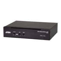
7 function switch Use this slide switch to set the unit’s mode to:
Auto: Shared (simultaneous) KVM control of the
computer at the Transmitter and Receiver console.*
RS-232 Config: The device is ready to be
configured via serial commands through the RS-232
port. When connected to a KVM over IP Access
Control Box (2XRT-0015G), users can enable /
disable control privileges of the connected
receivers.
Local: Only the local Transmitter has KVM control
of the computer. The Receiver’s KVM access to the
computer is locked.
Note: In Auto mode, RS-232 and audio functions will
work on the Receiver but not on the Transmitter.
8 RS-232 port This RS-232 serial port is for connecting to a serial
terminal.
9 console ports The unit’s USB keyboard and USB mouse plug into
these ports.
10 SFP slot The Gigabit Ethernet (GbE) optical fiber cable that
connects the unit to the LAN plugs in here.
11 DVI-I output The cables from the local DVI monitors plug in here.
12 power jack Connect a second power source for power
redundancy.
No. Component Description
 Loading...