8. Lamp and lamp house
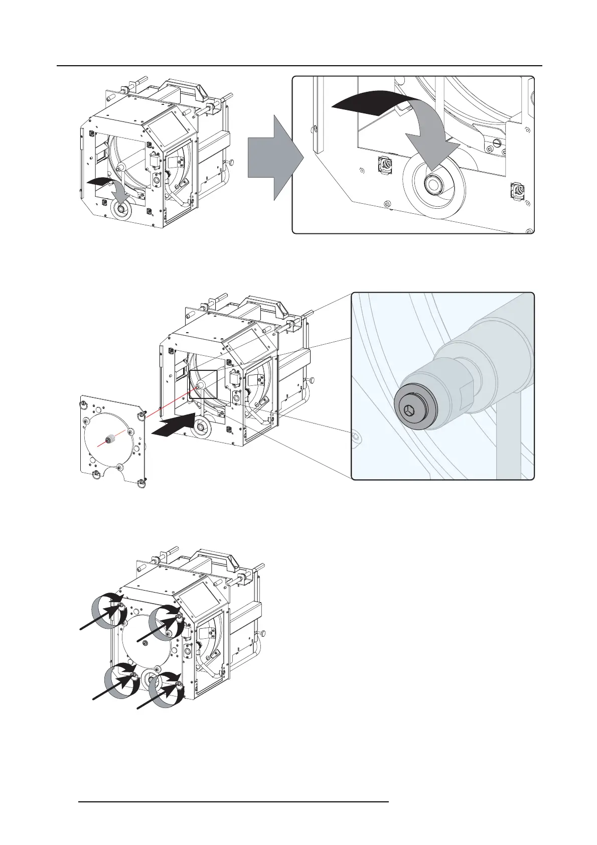
Image 8-20
Anode socket installation
7. R einstall the UV blocker assembly as illustrated. M ake sur e that the xenon lamp is properly supported by the lamp supporting
mechanism in the centre of the UV blocker. Use the opening at the side of the Lamp House to guide the supporting pin of the
xenon lam p into th e anode supporting mechanism.
Image 8-21
UV blocker installation
8. S ecur e the UV blocker by fastening the four reta ining thumbscrews as illustrated.
Note: Please ensure that the thumb screws turning wires are flush with the cover or interference will occur while in serting the
lamp house into the projector.
Image 8-22
Secure UV blocker
9. Fas ten the cathode si
de of the xenon lamp using a hexagon soc ket head screw M6 x 40 and a plain washer as illustrated. Use a
torque of 2,5 Nm (1,84 lbf*ft) to fasten the hexagon socket head screw. Use for that a torque wrench w ith a 5 mm Allen socket.
Caution: Make sure that the both pins of the cathode adapter remain enga ged in the foreseen slots. Use on e hand to keep
the xenon lamp into
position w hile inserting the hex agon socket head screw.
130
R5905312 HDF W SERIES 24/01/2013

 Loading...


